F4-XPM Expansion Modules Installation Guide
Application
The F4-XPM series expansion I/O modules can serve
in one of two capacities depending on where they are
installed in the system. When installed on the Sensor/
Actuator (SA) Bus of an equipment controller, an XPM
expands the input and output interfaces that can be
used with that equipment controller. When installed on
the Field Controller (FC) Bus of a FX-SNC, an XPM can be
used as I/O point multiplexors to support monitoring and
control from a FX-SNC. The point multiplexor can also
be useful for sharing points between other equipment
controllers on the FC Bus using peer-to-peer connectivity.
XPMs operate on an RS-485 BACnet MS/TP Bus and are
BACnet Testing Laboratory (BTL) listed and certified to the
BACnet Smart Actuator (B-SA) profile.
Communications Protocols
The XPM expansion modules can communicate using
BACnet MS/TP, or wireless Zigbee
®
using a ZFR/ZFR Pro
Wireless Field Bus Router (on the FC Bus only). By default,
the XPM expansion modules communicate using the
BACnet MS/TP protocol. The BACnet protocol is a standard
for ANSI, ASHRAE, and the International Standards
Organization (ISO) for building controls. To configure
these expansion modules in a wireless application
installation, see Configuring wireless communications.
Note: Using Controller Configuration Tool (CCT)
10.1 and later, FX equipment Controllers can be
configured to communicate using either the BACnet
MS/TP or the N2 field bus networking protocol.
The operation of an XPM on the SA Bus of an
equipment controller is not affected by the selection
of the BACnet MS/TP or the N2 protocol in the host
controller.
North American Emissions Compliance
United States
This equipment has been tested and found to comply
with the limits for a Class A digital device pursuant to
Part 15 of the FCC Rules. These limits are designed
to provide reasonable protection against harmful
interference when this equipment is operated in a
commercial environment. This equipment generates,
uses, and can radiate radio frequency energy and, if not
installed and used in accordance with the instruction
manual, may cause harmful interference to radio
communications. Operation of this equipment in a
residential area may cause harmful interference, in which
case the users will be required to correct the interference
at their own expense.
Canada
This Class (A) digital apparatus meets all the
requirements of the Canadian Interference-Causing
Equipment Regulations.
Cet appareil numérique de la Classe (A) respecte toutes
les exigences du Règlement sur le matériel brouilleur du
Canada.
Installation
Observe the following guidelines when installing an XPM
expansion module:
• To minimize vibration and shock damage transport the
expansion module in the original container.
• Verify that all parts shipped with the expansion module.
• Do not drop the expansion module or subject it to
physical shock.
Parts included
• One XPM expansion module with removable terminal
blocks (Input/Output, Power and SA bus terminal
blocks)
• One installation guide sheet
Materials and special tools needed
• Three fasteners appropriate for the mounting surface
(M4 screws or #8 screws)
• One 20 cm (8 in.) or longer piece of 35 mm DIN rail and
appropriate hardware for DIN rail mount (only)
• Small straight-blade (1/8 in. or 3.2 mm) or Philips #2
screwdriver for securing wires in the terminal blocks
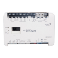
Physical features
The following figures display the physical features of XPM
expansion modules, and the accompanying table provides
a description of the physical features and a reference to
further information where required.
*241014302155-*
Part No. 24-10143-02155 Rev -
2020-11-11
(Barcode for factory use only)
F4-XPM04060, F4-XPM09090, F4-XPM18000