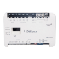
Figure 1: XPM09090 and XPM04060 Physical Features
(XPM04060 model shown)
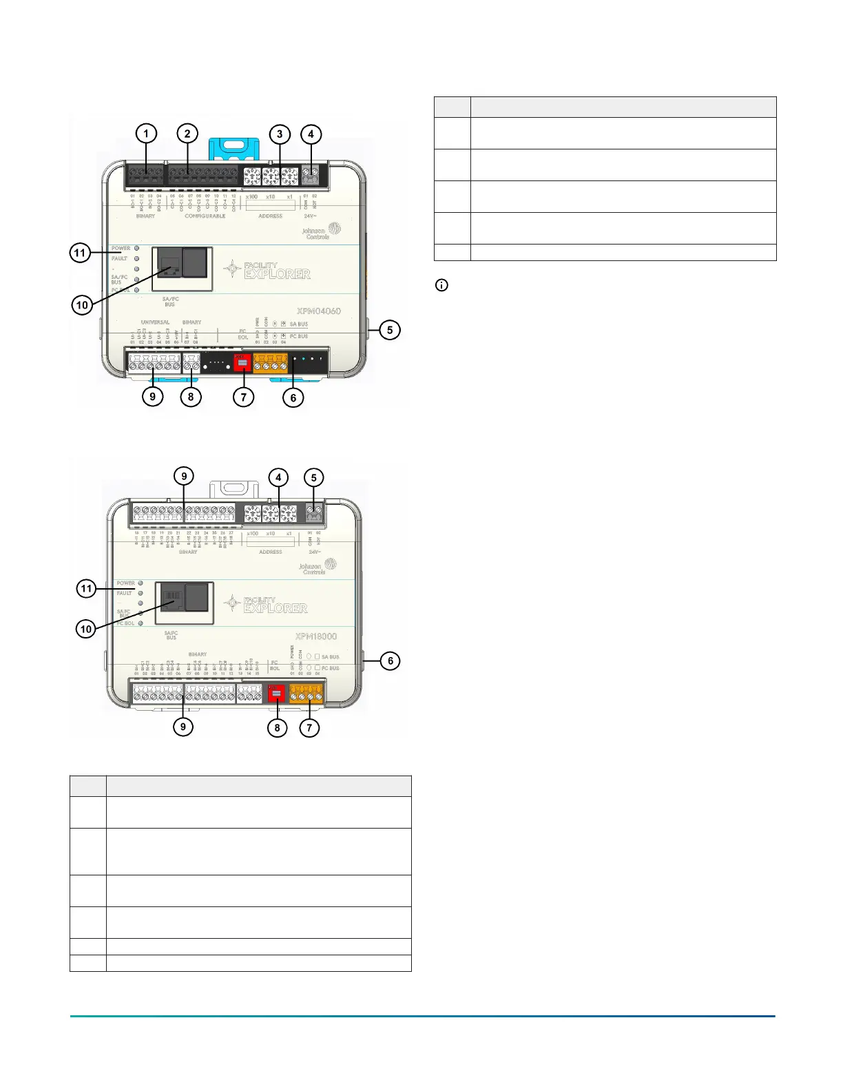
Figure 2: XPM18000 Physical Features
Table 1: Physical features of expansion modules
Physical Feature: Description and References
1
Binary Output (BO) Terminal Block: Black terminals. Only
present on XPM09090 and XPM04060 models. See Table 2.
2
Configurable Output (CO) Terminal Block: Black terminals.
Only present on XPM09090 and XPM04060 models. See
Table 2.
4
Device Address Rotary Switch Block: Decimal Addressing
See Setting the device address.
5
Supply Power Terminal Block: Gray terminals; 24 VAC,
Class 2. See Figure .
6 Cover Lift Tab. See Removing the expansion module cover.
7 SA/FC Bus Terminal Block: Orange terminal. See .
Table 1: Physical features of expansion modules
Physical Feature: Description and References
8
End-of-Line (EOL) Switch. See Setting the End-of-Line
(EOL) switch.
9
Binary Input (BI) Terminal Block: White terminals. See
Table 2.
10
Universal Input (UI) Terminal Block: Only present on
XPM09090 and XPM04060 models. See Table 2.
11
Sensor Actuator (SA) Bus/Field Controller (FC) Bus Port
(RJ-12 6-pin Modular Jack). See .
12 LED Status Indicators. See LED status and states.
Note: Analog Output (AO) Terminal Block (Black
terminal) is only present on XPM09090 model. See
Table 2.
Mounting
Observe the following guidelines when mounting an
expansion module:
• Ensure the mounting surface can support the
expansion module, DIN rail, and any user-supplied
enclosure.
• Mount the expansion module horizontally on 35 mm
DIN rail whenever possible.
• Mount the expansion module in the proper mounting
position.
• Mount the expansion module on a hard, even surface
whenever possible in wall-mount applications.
• Use shims or washers to mount the expansion module
securely and evenly on the mounting surface.
• Mount the expansion module in an area free of
corrosive vapors and observe the Ambient Conditions
requirements in Table 12.
• Provide for sufficient space around the expansion
module for cable and wire connections for easy cover
removal and good ventilation through the expansion
module (50 mm [2 in.] minimum on the top, bottom,
and front of the expansion module).
• Do not mount the expansion module on surfaces prone
to vibration, such as duct work.
• Do not mount the expansion module in areas where
electromagnetic emissions from other devices or wiring
can interfere with expansion module communication.
On panel or enclosure mount applications, observe the
following additional guidelines:
• Mount the expansion module so that the enclosure
walls do not obstruct cover removal or ventilation
through the expansion module.
• Mount the expansion module so that the power
transformer and other devices do not radiate excessive
heat to the expansion module.
• Do not install the expansion module in an airtight
enclosure.
F4-XPM Expansion Modules Installation Guide2