RXF ROTARY SCREW COMPRESSOR UNITS
INSTALLATION
070.410-IOM (JAN 12)
Page 9
Liquid line sizes and the additional receiver volume (quanti-
ty of refrigerant required for 5 minutes of liquid injection oil
cooling) are given in the following table:
FLOW
RXF
LIQ. LINE SIZE*
RATE LIQUID
REFRIG MODEL
PIPE TUBING
(lb) VOLUME
SCH 80 OD 5 MIN CU. FT
R-717
HIGH
STAGE
12 1/2 – 10 0.3
15 1/2 – 12.5 0.4
19 1/2 – 15 0.4
24 1/2 – 20 0.6
30 1/2 – 25 0.7
39 1/2 – 30 0.8
50 3/4 – 40 1.1
58 3/4 – 47 1.3
68 3/4 – 55 1.6
85 3/4 – 70 2.0
101 3/4 – 80 2.3
R-507
HIGH
STAGE
12 3/4 7/8 17 0.3
15 3/4 7/8 20 0.3
19 3/4 7/8 22 0.4
24 3/4 7/8 31 0.5
30 3/4 7/8 36 0.6
39 3/4 7/8 42 0.7
50 1¼
1C\,
56 0.9
58 1¼
1C\,
68 1.1
68 1¼
1C\,
78 1.2
85 1¼
1C\,
97 1.5
101 1¼
1C\,
120 1.9
R-717
BOOSTER
12 1/2 – 2.0 0.1
15 1/2 – 2.5 0.1
19 1/2 – 3.5 0.1
24 1/2 – 4.5 0.1
30 1/2 – 5.5 0.2
39 1/2 – 6.5 0.2
50 1/2 – 8.5 0.3
58 1/2 – 10 0.3
68 1/2 – 12 0.3
85 1/2 – 15 0.4
101 1/2 – 18 0.5
R-507
BOOSTER
12 3/8 1/2 5.5 0.1
15 3/8 1/2 6 0.1
19 3/8 1/2 7 0.1
24 3/8 1/2 10 0.2
30 3/8 1/2 11 0.2
39 3/8 1/2 13 0.2
50 3/4 7/8 17 0.3
58 3/4 7/8 23 0.4
68 3/4 7/8 26.5 0.4
85 3/4 7/8 33 0.5
101 3/4 7/8 40.5 0.6
* 100 ft. liquid line. For longer runs, increase line size accordingly.
High-stage compressor units may be supplied with single-port
(low Vi, side, or closed thread) or dual-port (low Vi and high Vi),
liquid injection oil cooling. Single port will be furnished for low
compression ratio operation and dual port for high compres-
sion ratio operation. Booster compressor units use single-port
(High Vi), liquid injection oil cooling due to the typically lower
compression ratios.
The control system on high-stage units with dual-port, liquid
injection oil cooling switches the liquid refrigerant supply to
the high port when the compres sor is operating at higher
compression ratios (3.5 Vi and above) for best efciency.
Where low compres sion ratios (low condensing pressures)
are anticipated, thermo syphon or water-cooled oil cooling
should be used.
It is imperative that an uninter-
rupted high-pres sure liquid refrig-
erant be provided to the injection
system at all times. Two items of EXTREME IMPORTANCE
are the design of the receiver/liquid injection supply and
the size of the liquid line. It is recommended that the
4. Welding should occur in two segments, from 6:00 to 12:00.
The maximum intersegment temperature should be 350°F.
Temperature should be veried with temperature indicating
crayon or equivalent.
5. The tting may be cooled with forced air to reduce the
temperature of the tting to 350°F or lower, prior to welding
the second segment.
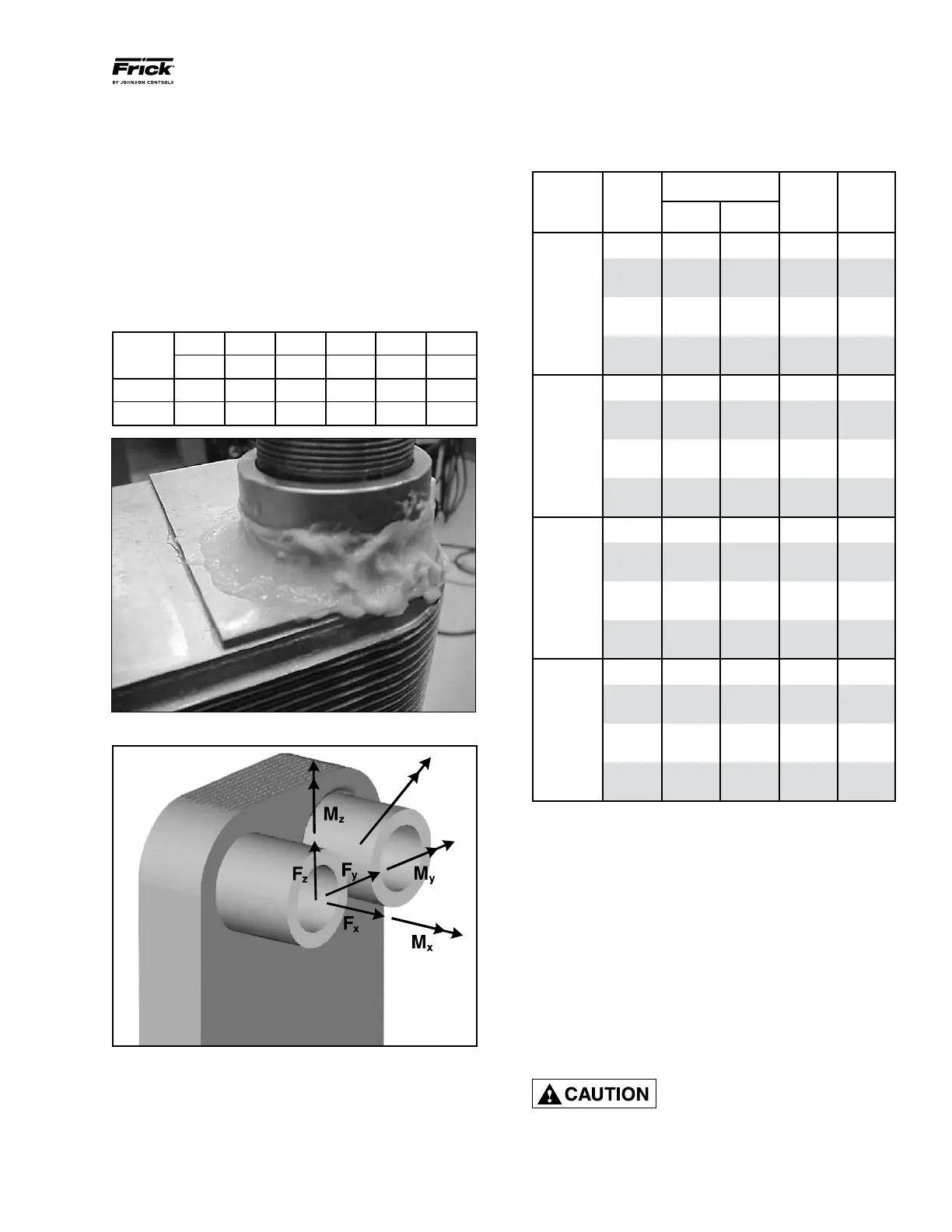
The maximum connection static forces and moments for Alfa
Nova heat exchangers are listed in the following table.Keep
these values in mind when designing your system. It is also
recommended to minimize connection loads when designing
piping systems. Also see Figure 6.
Fx Fy Fz Mx My Mz
(lb
f
) (lb
f
) (lb
f
) (lb
f
ft) (lb
f
ft) (lb
f
ft)
ANHP52 202 13 13 57 32 32
ANHP76 292 22 22 103 58 58
.
Figure 5 - Application of heat-sink paste before welding
Figure 6 - Maximum static forces and moments
LIQUID INJECTION OIL COOLING
The liquid injection system provided on the unit is self-con-
tained but requires the connection of the liquid line sized as
shown in the table.

 Loading...


