RXF ROTARY SCREW COMPRESSOR UNITS
INSTALLATION
070.410-IOM (JAN 12)
Page 8
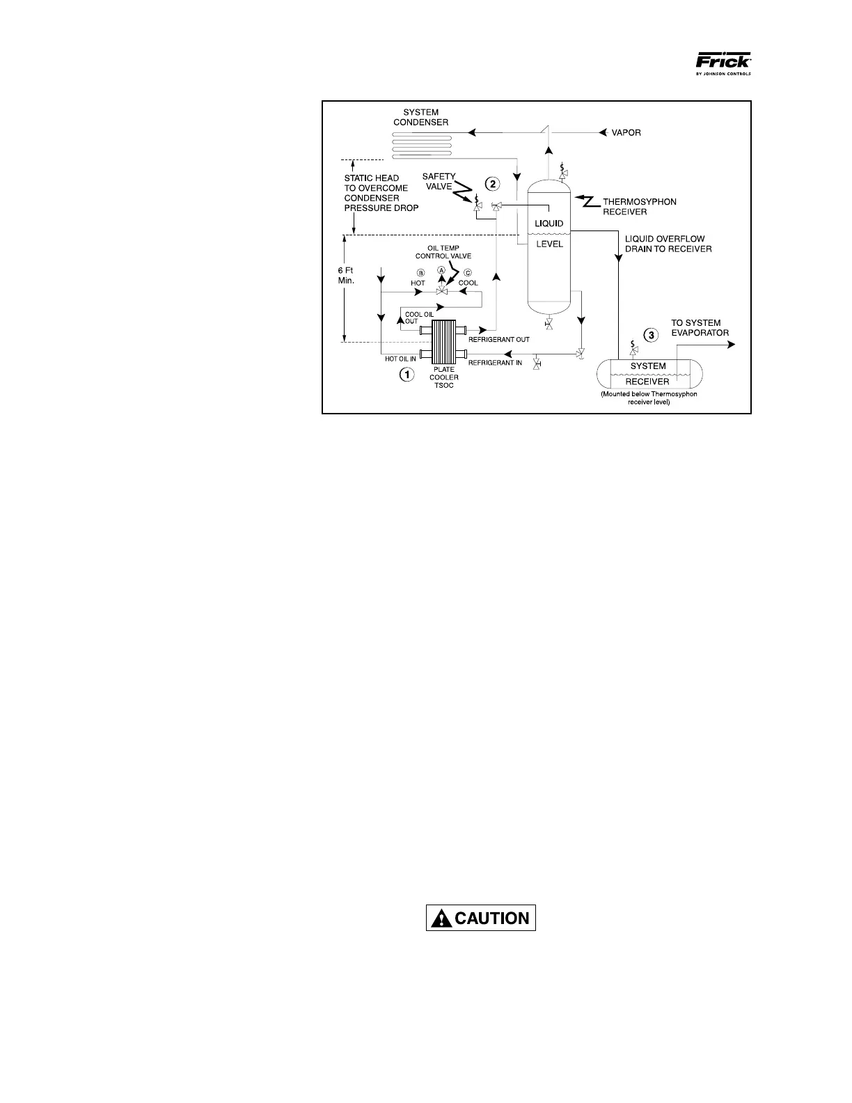
Figure 4
THERMOSYPHON OIL COOLING
EQUIPMENT: The basic equipment required for
a thermo syphon system consists of:
1. A source of liquid refrigerant at condens-
ing pressure and temperature located in close
prox imity to the unit to minimize piping pres-
sure drop.
The liquid level in the refrigerant source must
be 6 to 8 feet above the center of the oil cooler.
2. A shell and tube or plate-type oil cooler with
a minimum 300 psi design working pressure on
both the oil and refrigerant sides.
Due to the many variations in refrigeration sys-
tem design and physical layout, several systems
for assuring the above two criteria are possible.
INSTALLATION: The plate-type thermo syphon oil
cooler with oil side piping and a thermo statical ly
controlled mixing valve are factory mounted and
piped. See Figure 4.
1.
Thermosyphon oil cooler is supplied with oil
side piped to the compressor unit and socket weld
ends supplied on the refrigerant side.
2. A refrigerant-side safety valve is required when refriger-
ant isolation valves are installed between the cooler and
thermosyphon receiver. If no valves are used between the
cooler and thermosyphon receiver, the safety valve on the
thermosyphon receiver must be sized to handle the volume
of both vessels. Then, the safety valve on the cooler vent
(liquid refrigerant side) can be eliminated.
3. System receiver must be mounted below thermosyphon
receiver level in this arrangement.
4. The refrigerant source, thermosyphon or system receiver,
should be in close proximity to the unit to minimize piping
pressure drop.
5. The liquid level in the refrigerant source must not be less
than 6 feet above the center of the oil cooler.
6. Frick recommends the installation of an angle valve in the
piping before the thermosyphon oil cooler to balance the
thermosyphon system. Frick also recommends the instal-
lation of sight glasses at the TSOC inlet and outlet to aid in
troubleshooting. The factory-mounted plate-type thermo-
syphon oil cooler requires a refrigerant-side drain valve to
be provided and installed by the customer.
The component and piping arrangement shown in Figure 3 is
intended only to illustrate the operating principles of thermo-
syphon oil cooling. Other component layouts may be better
suited to a specic installation. Refer to publication E70-900E
for additional information on Thermosyphon Oil Cooling.
WATER-COOLED OIL COOLING
The plate-type water-cooled oil cooler is mounted on the
unit complete with all oil piping. The customer must supply
adequate water to the oil cooler.
Frick recommends a closed-loop system for the waterside
of the oil cooler. Careful attention to water treatment is es-
sential to ensure adequate life of the cooler if cooling tower
water is used. It is imperative that the condition of cooling
water and closed-loop uids be analyzed regularly and as
necessary and maintained at a pH of 7.4, but not less than
6.0 for proper heat exchanger life. After initial start-up of
the compressor package, the strainer at the inlet of the oil
cooler should be cleaned several times in the rst 24 hours
of operation.
In some applications, the plate-type oil cooler may be sub-
jected to severe water conditions, including high temperature
and/or hard water conditions. This causes accelerated scal-
ing rates which will penalize the performance of the heat
exchanger. A chemical cleaning process will extend the life
of the heat exchanger. It is important to establish regular
cleaning schedules.
Cleaning: A 3% solution of Phosphoric or Oxalic Acid is rec-
ommended. Other cleaning solutions can be obtained from
your local distributor, but they must be suitable for stainless
steel. The oil cooler may be cleaned in place by back ushing
with recommended solution for approximately 30 minutes.
After back ushing, rinse the heat exchanger with fresh water
to remove any remaining cleaning solution.
FIELD WELDING INSTRUCTIONS FOR TSOC AND WCOC: The
heat exchanger body is constructed in stainless steel, while
the stub connections are carbon steel. The highly polished
stub connections can give the appearance of stainless steel.
The following are requirements for welding to the socket
weld ttings on Plate heat exchangers:
1. Use a heat sink paste around the base of the connection.
These are available from a number of suppliers of welding
materials.
Heat-sink paste must be applied
around the base of the connection
prior to welding.See Figure 5.
2. Two-pass welding is required; stagger start/stop region;
welding procedure in accordance with ASME Section 9.
3. If possible use gas protection, when welding, to avoid
oxidation of the surface. As it is rarely possible to clean the
root side of the weld by grinding or brushing to remove the
root oxide, it is optimal to use root gas.
 Loading...


