VYPER
™
VARIABLE SPEED DRIVE
INSTALLATION
S100-200 IOM (MAY 08)
Page 14
CONFIGURATION:
The Frick Vyper
™
is internally cooled with a factory calibrated
liquid cooling circuit which offers many advantages over tradi-
tional air-cooled systems. The liquid circuit provides precisely
controlled coolant temperatures to the heat generating com-
ponents and delivers coolant into locations that no air-over
fan could penetrate. The Vyper
™
liquid-cooling arrangement
performs independently of fl uctuating ambient conditions. The
NEMA 4 Indoor-rated cabinet seals the internal electronics
and piping from corrosive refrigerant vapors while provid-
ing superior cooling for the internal electronic components.
Effi cient liquid cooling also allows for smaller cabinet size
and longer component life than traditional air-cooled units.
Either plant condenser water or a facility supplied Glycol loop
subsequently removes the heat in the coolant via the heat
exchanger located at the back of the cabinet.
VYPER
™
COOLING LOOP
While the compressor is running, the Quantum
™
LX control
panel monitors the temperature of Vyper
™
drive coolant. With
this information, the Quantum
™
LX delivers a 4-20 mA signal
to the 3-way mixing valve, based on the setpoints of a PID
loop output from the Quantum
™
LX. This signal will maintain
the Vyper
™
coolant temperature at the control setpoint for
the PID loop. This setpoint will be set at 110°F at the factory.
There are also low and high temp alarms and shutdowns as-
sociated with the Vyper
™
coolant temperature reading. These
wil also be factory set for a Low Temp. alarm and shutdown
at 85°F and 80°F with a 90 second delay, when running.
The High Temp. Alarm and shutdown will be factory set at
125°F and 130°F with a 30 second delay when running. If
the Vyper
™
coolant temperature drops too low, condensation
may occur, damaging vital electronic components.In addi-
tion to controlling the Vyper
™
cabinet cooling system, the
Quantum
™
LX panel also monitors four temperatures from
the Vyper
™
cabinet. If any of these temperatures rise too
high, the Quantum
™
LX panel will go to a Stop Load condi-
tion, preventing either the slide valve position or motor speed
from increasing. If the temperature continues to rise, the
Quantum
™
LX panel will next go to a Force Unload condition.
In this situation, the slide valve will unload to lower the motor
torque required, in an effort to drop the temperature in the
panel. Below is a chart showing the Stop Load and Force
Unload temperatures as well as the temperatures where the
Vyper
™
cabinet will automatically shut down.
Location Stop Start Force Unload Shutdown
Base plate
Temp Converter
160°F 165°F 175°F
Heat Sink Temp 155°F 160°F 170°F
Harmonic Filter 130°F 135°F 145°F
Base plate Temp 160°F 165°F 175°F
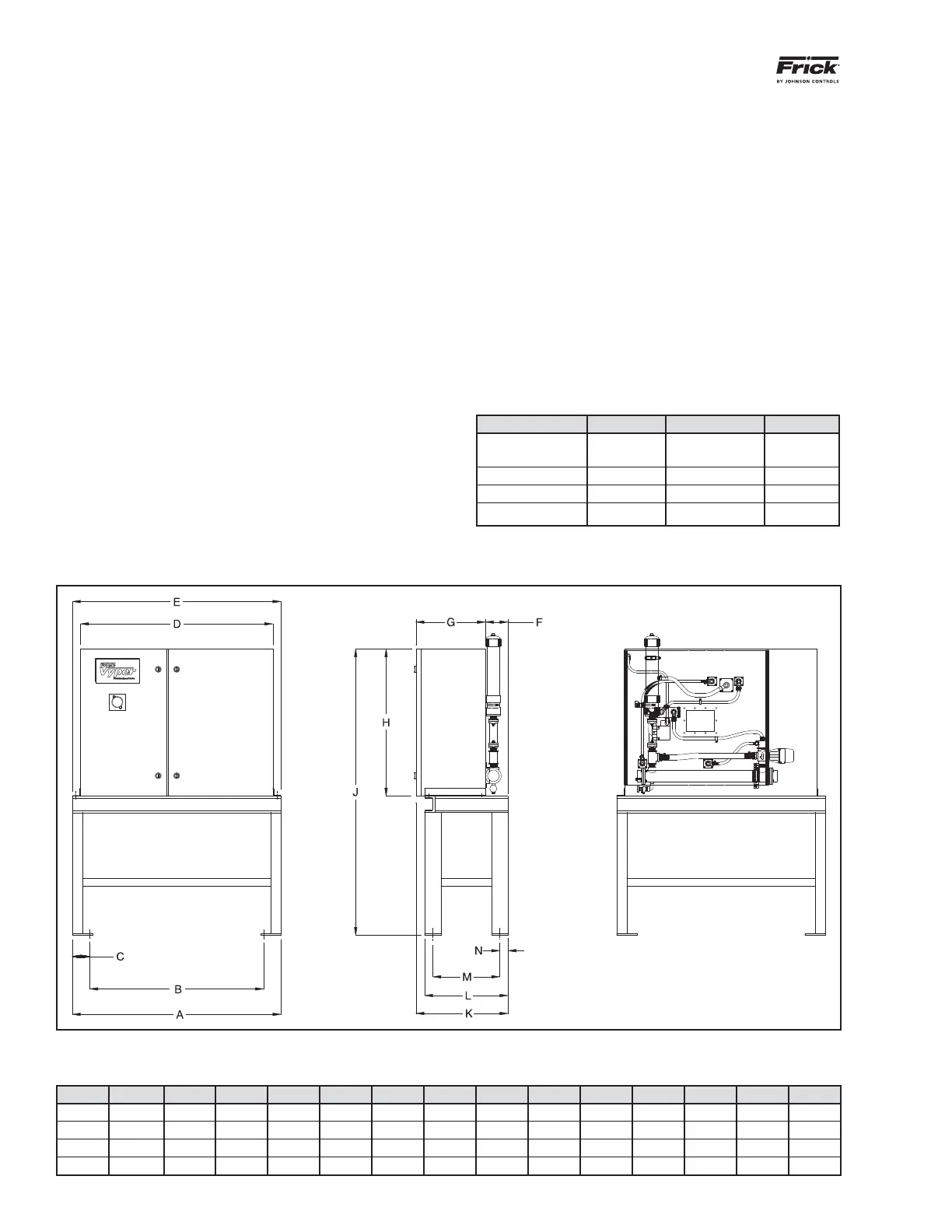
VYPER
™
CONFIGURATIONS -Liquid Cooled
HP Freq ABCDEFGHJKLMN
254 50 51 42.5 4.25 47 51 5.5 17 36 70 22.5 20.4 16.4 2
305 60 51 42.5 4.25 47 51 5.5 17 36 70 22.5 20.4 16.4 2
362 50 58 49.5 4.25 54 58 5.5 19.1 41 75 24.6 22.5 18.5 2
437 60 58 49.5 4.25 54 58 5.5 19.1 41 75 24.6 22.5 18.5 2
Remote-mounted confi guration is shown. Package-mount dimensions are identical except for the elimination of the stand. Coolant
connections to the Heat Exchanger are 1½ NPT.
 Loading...

