VYPER
™
VARIABLE SPEED DRIVE
MAINTENANCE
S100-200 IOM (MAY 08)
Page 50
Fault 5: Interface Board Panel Communications Loss
Message
Quantum: “Fault 5”
Quantum LX: “VSD Interface Board to Panel Comms Loss”
This fault occurs when the Frick Interface Board loses com-
munications from the Quantum
™
LX Control Panel, meaning
it has not received any data for a period of fi fteen seconds.
It is only applicable in automatic mode.
Fault 7: Vyper Initialization
Message
Quantum: “Fault 7”
Quantum LX: “VSD Initialization Fault”
At power-up, all the boards go through a process called ini-
tialization. At this time, memory locations are cleared, jumper
positions are checked, and serial communications links are
established. There are many causes for an unsuccessful
initialization. The following check list should aid in determining
why the initialization has not been completed:
• The Control Center and the Vyper
™
must be energized at
the same time. The practice of pulling the fuse in the con-
trol center to make wiring changes will create a problem.
Power-up must be done by closing the main disconnect
on the Vyper
™
cabinet with all fuses in place. Be sure you
do not have an open fuse, causing loss of power to the
Vyper
™
Logic board which can cause this fault.
• The EPROMs must be correct for each board, and they
must be correctly installed. There are a total of seven (7)
EPROMs in each Vyper
™
system. These EPROMs are
created as a set, and cannot be intermixed. All pins must
be properly inserted into the EPROM sockets.
• Serial data must be established. (See: Serial Communication
Fault” error code). If communications between the Vyper
™
Logic, Filter Logic, and Interface Boards and Quantum panel
does not take place during initialization, Fault 5 message
will appear before any other message can be generated.
Check to see that the serial communications have been
established by selecting the Motor information screen veri-
fying the drive horsepower. A zero displayed value for this
parameter (and all other Vyper
™
parameters) indicates a
serial communications link or EPROM problem.
• If the Harmonic Filter option is included, make sure the
Harmonic Filter Logic board is not in continuous reset.
This will be evidenced by the LEDs on the fi lter logic
board alternately blinking. To rule out the Harmonic Filter
as the cause of initialization failure, disconnect the fi lter
by switching the fi lter logic board’s SW1 switch to the OFF
position, and removing the 16 wire ribbon cable between
the Harmonic Filter logic and Vyper
™
Logic Board.
Fault 8: Vyper - Stop Contacts
Message
Quantum: “Fault 8 “
Quantum LX: “VSD Stop Contacts Fault “
This fault occurs if the No Fault signal from the Vyper
™
is low.
It indicates a fault is present at the Vyper
™
or the Harmonic
Filter, but the communications data contains no Vyper
™
fault
data for twenty seconds. The Frick Interface Board will send
Initialize data requests while this fault is active.
Whenever the Vyper
™
initiates a fault, it fi rst opens the K1
relay on the Vyper
™
Logic board. When the relay opens,
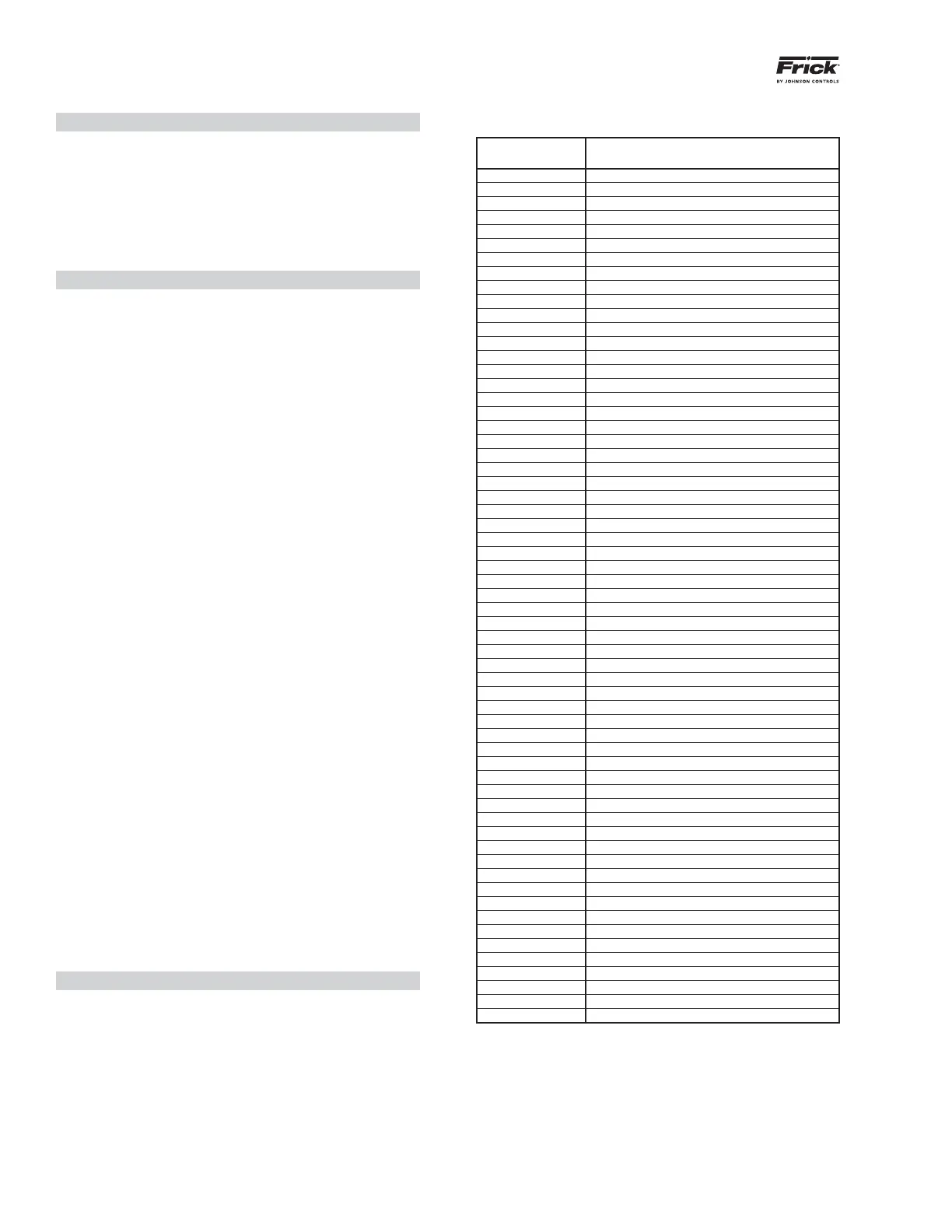
FRICK VYPER
™
FAULT CODES
Quantum
™
LX
Failure Code
Quantum
™
LX Failure Message
1 VSD Interface Board Power Supply Fault
2 VSD Interface Board Loss of Motor Current
3 VSD Interface Board Motor Current > 15%
4 VSD Interface Board Run Signal Fault
5 VSD Interface Board to Panel Comms Loss
7 VSD Initialization Fault
8 VSD Stop Contacts Fault
9 Harmonic Filter Logic Board Or Comms Fault
10 Harmonic Filter High Total Demand Distortion
11*
High Phase B Inverter Baseplate Temperature
12*
High Phase C Inverter Baseplate Temperature
13*
Low Phase B Inverter Baseplate Temperature
14*
Low Phase C Inverter Baseplate Temperature
17 VSD High Phase A Instantaneous Current
18 VSD High Phase B Instantaneous Current
19 VSD High Phase C Instantaneous Current
21 VSD Phase A Gate Driver Fault
22 VSD Phase B Gate Driver Fault
23 VSD Phase C Gate Driver Fault
24 VSD Single Phase Input Power Fault
27 VSD 105% Motor Current Overload Fault
28 VSD High DC Bus Voltage Fault
29 VSD Logic Board Power Supply Fault
33 VSD Low DC Bus Voltage Fault
34 VSD DC Bus Voltage Imbalance Fault
35 VSD High Internal Ambient Temp Fault
36 VSD High Phase A Inverter Baseplate Temp
VSD High Phase B Inverter Baseplate Temp
VSD High Phase C Inverter Baseplate Temp
37 VSD Logic Board Processor Fault
38 VSD Run Signal Fault
39 VSD High Converter Heatsink Temp Fault
40 VSD Invalid Current Scale Selection
41 VSD Low Phase A Inverter Baseplate Temp
VSD Low Phase B Inverter Baseplate Temp
VSD Low Phase C Inverter Baseplate Temp
42 VSD Serial Communication Fault
43 VSD Precharge Lockout Fault
44 VSD Low Converter Heatsink Temp Fault
45 VSD Current Imbalance Fault
46 VSD Precharge - DC Bus Voltage Imbalance
47 VSD Precharge - Low DC Bus Voltage 2
48 VSD Precharge - Low DC Bus Voltage 1
50 Harmonic Filter High DC Bus Voltage Fault
51 Harmonic Filter High Phase C Current Fault
52 Harmonic Filter High Phase B Current Fault
53 Harmonic Filter High Phase A Current Fault
54 Harmonic Filter Phase Locked Loop Fault
56 Harmonic Filter Logic Board Power Supply
65 Harmonic Filter Precharge - High DC Bus Voltage
66 Harmonic Filter Precharge - Low DC Bus Voltage
67 Harmonic Filter DC Current Transformer 1
68 Harmonic Filter DC Current Transformer 2
69 Harmonic Filter High Baseplate Temp Fault
71 Harmonic Filter Low DC Bus Voltage
75 Harmonic Filter DC Bus Voltage Imbalance
76 Harmonic Filter 110% Input Current Overload
77 Harmonic Filter Run Signal Fault
81 VSD Interface Board NovRAM Failure
83 Harmonic Filter Serial Communication
84 Harmonic Filter Input Frequency Out of Range
* 437 HP drives only
the voltage between wire #53 and #16 will be 115 VAC. If
wire #53 to #16 circuit ever opens without receiving an ac-
companying cause for the trip over the serial link (within 11
communication tries, approximately 22 seconds), this Fault
Code will be displayed. A loose wire is often the cause of
this problem. Check the #1 to #53 horseshoe jumper in the
Control Center and all other wiring involving #53 and #16.
This fault may be replaced with a Serial Communications
fault if the serial link has failed.
 Loading...

