VYPER
™
VARIABLE SPEED DRIVE
INSTALLATION
S100-200 IOM (MAY 08)
Page 20
EXTERNAL POWER AND CONTROL WIRING
External power and control signals must be brought in and
out of the Vyper
™
variable speed drive. The unit requires the
wiring to be properly installed to supply power to the unit for
processing. The Vyper
™
also outputs processed power to the
motor of a compressor package. The two connection points
are at the following locations:
INPUT POWER CONNECTION For Remote-mounted units,
the Input power junction is located on the upper left side of
the cabinet. This location provides a junction for three power
cables, T1, T2, and T3. Incoming Power leads (See Figure
11) must have their ends stripped of insulation for insertion
in the junction area.
Be sure there is no power running
through the leads during installation!
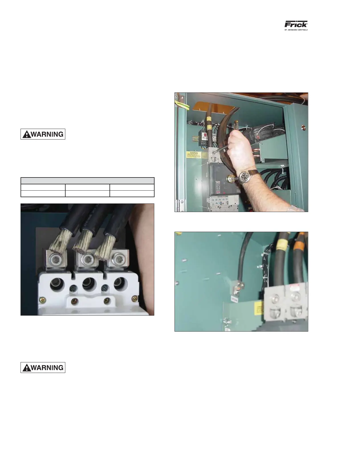
The external power leads may be inserted into the top of the
circuit breaker and then fastened via a hex style wrench (See
Figure 12). In addition the grounding connection is adjacent
to the external power connections and located on the top of
the left wall of the cabinet. (See Figure 13)
Input Power Lead Torque Requirement
Wire Size Material Torque
4-4/0 Cu 275 in-lb
Figure 11 - Insulation stripped from power leads
OUTPUT POWER CONNECTION (Remote Mount) The wire
leads from the motor must be prepared prior to installation.
The preparation involves stripping lead insulation for the mo-
tor to expose the copper wire within the lead. NOTE: About
½" to 1" of exposed wire is recommended.
Before working on the motor wir-
ing, be certain that the Drive has
been powered down for at least fi ve
minutes. This allows the internal capacitors/resistors to
discharge the DC bus and allow for safe maintenance
of the unit. Failure to do so may cause serious injury
or death. Also ensure that all power has been removed
from the leads while connecting to the Vyper
™
.
The motor leads must be brought in from the top of the unit.
Carefully remove the panel, which covers the motor lead entry
point, by removing the screws. Wires may then be run into
the interior of the cabinet. Be sure to leave enough relief in
the leads so no undue stresses are transferred to the motor
connection location in the interior of the unit. The attachment
points are T1, T2, and T3. They are labeled in the body of
the cabinet at the motor lead attachment points. Insert the
stripped connectors and tighten with a small wrench. Con-
nectors should not loosen when given a moderate tug by
hand.
Figure 12 - Fastening the power lead
Figure 13 - Grounding Lug
For remote-mounted units it is required that a dV/dt “snub-
ber” fi lter be installed between the Vyper
™
and the motor
to ensure a clean power signal into the motor. This fi lter is
required for all remote-mounted systems with power leads
between 3-50 feet in length.
OUTPUT POWER CONNECTION (Package Mount)
Package-mounted Vyper
™
drives have a different output
confi guration than the remote-mount Vyper
™
. The Package-
mounted Vyper
™
uses 3/8" terminal lugs for the output power
connection to the compressor motor. Appropriate motor lead
hardware should be used to make the connections. The at-
tachment lugs are labeled T1, T2, and T3 and are located on
the back right wall of the interior of the Vyper
™
cabinet (See
Figure 14). The power wiring emerges from the rectangular
 Loading...

