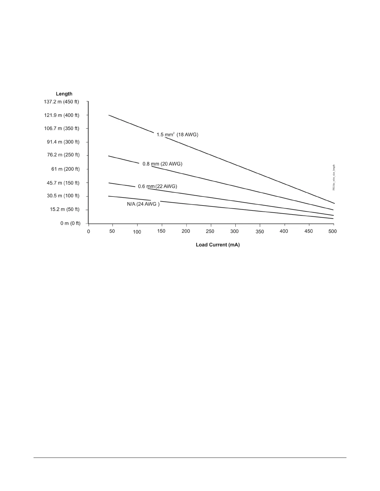
Maximum Cable Length versus
Load Current
Use Figure 8 to estimate the maximum cable length
relative to the wire size and the load current (in mA) when
wiring inputs and outputs.
Note: Figure 8 applies to low-voltage (<30V) inputs and
outputs only.
Figure 8: Maximum Wire Length for Low-Voltage (<30V) Inputs and Outputs by Current and Wire Size
SA/FC Bus and Supply Power
Wiring Guidelines
Table 5 provides information about the functions, ratings,
and requirements for the controller communication bus
and supply power terminals; and guidelines for wire sizes,
cable types, and cable lengths when wiring the controller
communication buses and supply power.
In addition to the guidelines in Table 5, observe these
guidelines when wiring an SA or FC bus and the 24 VAC
supply power:
• Run all low-voltage wiring and cables separate from
high-voltage wiring.
• All SA and FC bus cables, regardless of wire size,
should be twisted, insulated, stranded copper wire.
• Shielded cable is strongly recommended for all SA
and FC bus cables.
•
Refer to the FX-PC Series Controller MS/TP
Communication Bus Technical Bulletin
(LIT-12011670) for detailed information regarding
wire size and cable length requirements for the SA
and FC buses.
10FX-PCX3731 Input/Output Module Installation Instructions