Table 5: Communications Bus and Supply Power Terminal Blocks, Functions, Ratings, Requirements, and
Cables
Recommended Cable Type
1
Function, Electrical Ratings/RequirementsTerminal
Labels
Terminal
Block/Port Label
FC Bus: 0.6 mm (22 AWG)
stranded, 3-wire twisted, shielded
cable recommended.
SA Bus: 0.6 mm (22 AWG)
stranded, 4-wire (2 twisted-pairs),
shielded cable recommended.
Note: On the SA Bus, the + and -
wire are one twisted pair,
and the COM and SA PWR
are the second twisted pair
of wires.
FC or SA Bus Communications+
-
FCBUS
2
or
SABUS
2
Signal Reference (Common) for FC or SA Bus
communications
COM
SHLD on FC Bus: Isolated terminal (optional shield drain
connection
SAP WR on SA Bus: 15 VDC power lead connection
SHLD
or
SAPWR
Bluetooth Commissioning Converter
retractable cable or 24 AWG 3-pair
CAT 3 Cable <30.5 m (100 ft)
RJ-12 6-Position Modular Connector provides:
FC or SA Bus Communications
FC or SA Bus Signal Reference and 15 VDC Common
Commissioning Converter or an FX-ZFR 1811 Wireless
Router
(Maximum total current draw for SA Bus is 240 mA.)
SA/FC BUS
2
(Port)
0.8 mm to 1.5 mm
2
(18 AWG) 2-wire
24 VAC Power Supply - Hot
Supplies 20-30 VAC (Nominal 24 VAC)
HOT24~
24 VAC Power Supply - Common
(Isolated from all other Common terminals on controller.)
COM
1
See Table 4 to determine wire size and cable lengths for cables.
2 The SA Bus and FC Bus wiring recommendations in this table are for MS/TP bus communications at 38,400 baud. For more
information, refer to the FX-PC Series Controller MS/TP Communications Bus Technical Bulletin (LIT-12011670).
Setup and Adjustments
Setting the Device Addresses
FX-PCX controllers are master devices on MS/TP (SA
or FC) buses. Before operating controllers on a bus, you
must set a valid and unique device address for each
controller on the bus. You set a controller's device
address by setting the positions of the switches on the
DIP switch block at the top of the controller (Figure 3).
Device addresses 4 through 127 are the valid addresses
for these controllers.
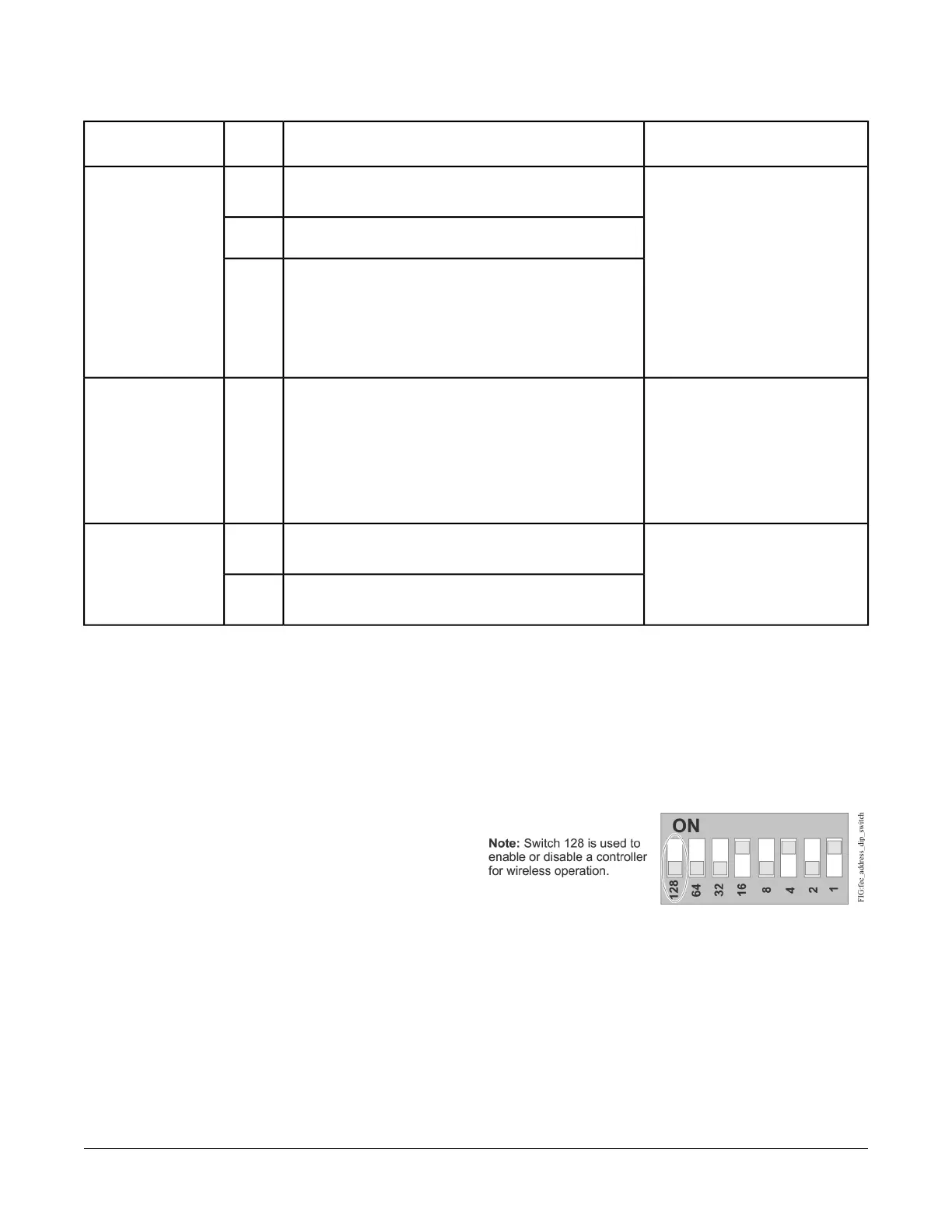
The DIP switch block has eight switches numbered 128,
64, 32, 16, 8, 4, 2, and 1. Switches 64 through 1 are
device address switches. Switch 128 is a mode switch
that enables a controller to operate on an FX-ZFR Series
Wireless Field Bus. Switch 128 must be set to off for all
hard-wired SA and FC bus applications. Set switch 128
to ON for wireless FC bus applications only.
Figure 9: Device Address DIP Switch Block Set to
Address 21
Note: All FX-PC series devices ship with switch 128 ON
and the remaining address switches off rendering
the controllers wired slave devices, which do not
operate on MS/TP buses, but will not interfere
with bus operation. Set a valid and unique device
address on the controller before applying power
to the controller on the bus.
To set the device addresses on FX-PCX controllers:
11FX-PCX3731 Input/Output Module Installation Instructions