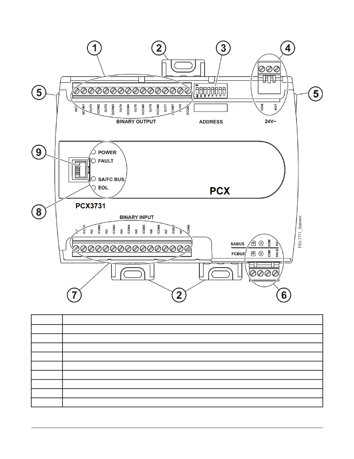
Figure 3: FX-PCX3731 Physical Features
Table 1: FX-PCX3731 Physical Features Callouts and Descriptions
Physical Feature: Description and ReferencesCallout
Binary Outputs (BOs) Terminal Block (See Table 3)
1
Mounting Clip (Three Total)2
Device Address DIP Switch Block (See Setting the Device Addresses)
3
24 VAC, Class 2 Supply Power Terminal Block (See Supply Power Terminal Block)
4
Cover Lift Tab (One of Two) (See Removing the Controller Cover)
5
Sensor Actuator (SA) Bus or Field Controller (FC) Bus Terminal Block (See SA/FC Bus Terminal Block)
6
Binary Inputs (BIs) Terminal Block (See Table 3)
7
LED Status Indicators (See Table 7)
8
Sensor Actuator (SA) Bus or Field Controller (FC) Bus Port (RJ-12 6-pin Modular Jack) (See SA/FC Bus Port)
9
3FX-PCX3731 Input/Output Module Installation Instructions