Johnson Controls, Inc. SLC Wiring Manual — P/N 51870:G 04/23/2009 51
Wiring a Sounder Base Intelligent Detector Bases
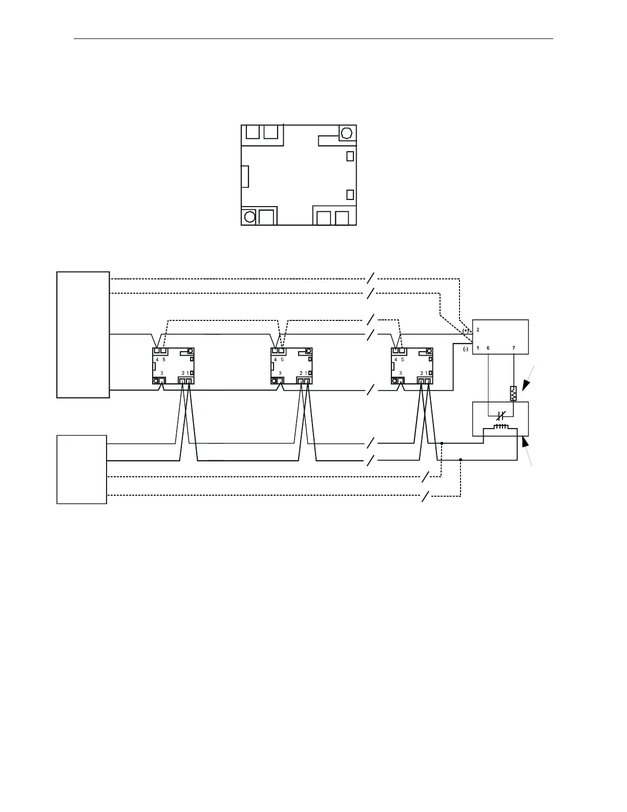
9.5 Wiring a Sounder Base
Figure 9.5 shows typical wiring of the B501BH, and B501BHT sounder bases.
Figure 9.5 Wiring of the B501BH/B501BHT Sounder Bases
B501BHWiring.wmf
Class A Optional Wiring
Optional Sounder Interconnect*
SLC B+
SLC B-
(-) Power
(+) Power
UL-listed
Compatible
FACP
Class A Optional Wiring
External
24V
Supply
Intelligent
Monitor
Module
UL-listed
EOL Relay
24V
UL-listed
EOL
Resistor
47K
*Grouping of up to 6 model B501BHT temporal tone sounder bases.
OUT
+4 –5
IN
-3
External supply
– 2 +1
45
321