description of the physical features and a reference
to further information where required.
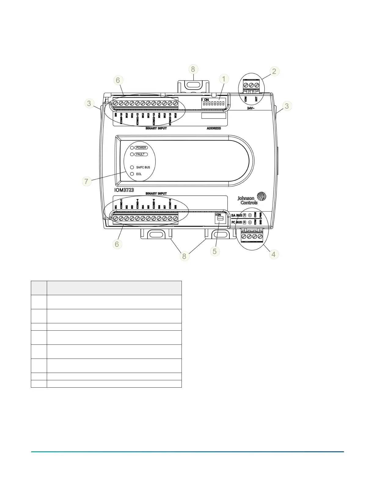
Figure 1: IOM3723 physical features
Table 1: IOM3723 features callout numbers and
descriptions
Callo
ut
Physical features: description and references
1
Device Address DIP Switch Block (see Setting the device
address)
2
24 VAC, Class 2 Supply Power Terminal Blocks (see Supply
power terminal block)
3 Cover Lift Tab (see Removing the expansion module cover)
4
Sensor Actuator (SA) Bus/Field Controller (FC) Bus
Terminal Block (see SA/FC bus terminal block)
5
End-of-Line (EOL) Termination Switch (see Setting the End-
of-Line (EOL) switch)
6
Binary Input (BI) Terminal Block (see Input and Output
wiring guidelines)
7 LED Status Indicators (see Table 7)
8 Mounting Clips
Mounting
Observe these guidelines when mounting an IOM
expansion module:
• Ensure the mounting surface can support the
expansion module, DIN rail, and any user-
supplied enclosure.
• Mount the expansion module horizontally on
35 mm (1.4 in.) DIN rail whenever possible.
• Mount the expansion module in the proper
mounting position (Figure 2).
• Mount the expansion module on a hard, even
surface whenever possible in wall-mount
applications.
• Use shims or washers to mount the expansion
module securely and evenly on the mounting
surface.
IOM3723 Input/Output Module Installation Guide2