I/O terminal blocks, ratings, and
requirements
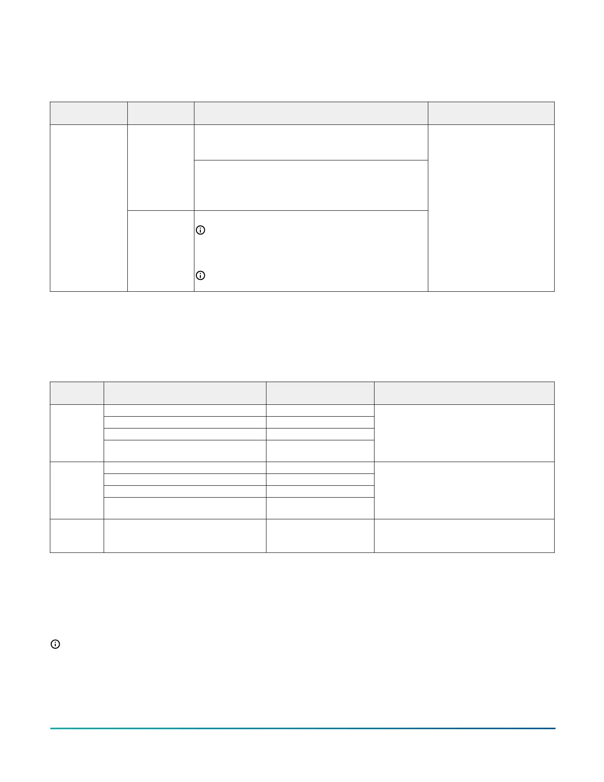
Table 2: IOM3723 terminal blocks, functions, ratings, requirements, and cables
Terminal block
label
Terminal label Function, ratings, requirements
Determine wire size and
maximum cable length
Binary Input - Dry Contact Maintained Mode
0.01 second minimum pulse width Internal 16 V, 10K ohm pull
up
INn
Binary Input - Pulse Counter/Accumulator Mode
0.01 second minimum pulse width
(50 Hz at 50% duty cycle)
Internal 16 V, 10K ohm pull up
BINARY INPUT
ICOM n
Binary Input Common for all Binary Input (IN) terminals
Note: All Binary ICOMn terminals share a common,
which is isolated from all other commons, except the
Configurable Output (CO) common (OCOMn) when the
CO is defined as an Analog Output.
Note: For all Binary ICOMn terminals, BI is isolated from
the FC bus common.
See Guideline A in Table 3.
Cable and wire length guidelines
The following table defines cable length guidelines for the various wire sizes that may be used for wiring low-
voltage (<30 V) input and outputs.
Table 3: Cable length guidelines
Guideline Wire size/Gauge and type
Maximum cable length
and type
Assumptions
1.0 mm (18 AWG) stranded copper 457 m (1,500 ft) twisted wire
0.8 mm (20 AWG) stranded copper 297 m (975 ft) twisted wire
0.6 mm (22 AWG) stranded copper 183 m (600 ft) twisted wire
A
0.5 mm (24 AWG) stranded copper 107 m (350 ft) twisted wire
100 mV maximum voltage drop
Depending on the cable and the connected
input device, you may have to define an offset
in the setup software for the input or output
point.
1.0 mm (18 AWG) stranded copper 229 m (750 ft) twisted wire
0.8 mm (20 AWG) stranded copper 137 m (450 ft) twisted wire
0.6 mm (22 AWG) stranded copper 91 m (300 ft) twisted wire
B
0.5 mm (24 AWG) stranded copper 61 m (200 ft) twisted wire
100 mV maximum voltage drop
Depending on the cable and the connected
input device, you may have to define an offset
in the setup software for the input or output
point.
C
See Figure 7 to select wire size/gauge. Use
stranded copper wire.
See Figure 7 to determine
cable length. Use twisted
wire cable.
N/A
Maximum cable length versus load
current
Use the following figure to estimate the maximum
cable length relative to the wire size and the load
current (in mA) when wiring inputs.
Note: The following information applies to low-
voltage (<30 V) inputs only.
IOM3723 Input/Output Module Installation Guide 7