6112628-UIM-B-0622
Johnson Controls Ducted Systems 11
Section X: Low voltage control connections
The 24 V power supply is provided by an internally wired low voltage
transformer that is standard on all models. If connecting the unit to a 208
V power supply, the low voltage transformer must be rewired to the 208 V
tap. See the Wiring diagram.
Field-supplied low voltage wiring can exit the unit through the top right
(when unit is vertical upflow) or the right side panel. See Figure 3.
Remove the knockout and pierce the foil faced insulation to allow wiring
to pass through. Use as small of a hole as possible to minimize air leak-
age. Install a 7/8 in. plastic bushing in the selected hole and keep low
voltage wiring as short as possible inside the control box.
To further minimize air leakage, seal the wiring entry point at the outside
of the unit. Connect the field wiring at the pigtails supplied with the air
handler. See Figure 20 to Figure 28 for system wiring.
Section XI: Blower speed connections
Adjust the blower motor speed to provide airflow within the minimum and
maximum limits approved for indoor coils, electric heat, and outdoor
units. Make speed tap adjustments at the motor terminal block.
See Table 13 for airflow data. Connect the motor wires to the motor
speed tap receptacle for the speed required.
The standard ECM motor operates when a 24 VAC signal is sent to any
of its five speed taps. If simultaneous 24 VAC inputs are present, the
motor operates at the highest speed tap that is energized. The lowest
speed is one and the highest speed is five.
The air handler comes factory-wired with the electric heat kit connected
to tap five for the heating speed. There are two speed tap wires for cool-
ing or heat pump blower speeds. The YEL/BLK wire is for first stage com-
pressor speed and the YEL wire is for full compressor speed. The RED
continuous fan speed wire is connected to speed tap one. If the lowest
speed tap (tap one) is needed for first stage compressor speed, leave the
continuous fan speed wire connected to speed tap one and let the room
thermostat provide the signal (through its G output) for first stage
compressor, as the room thermostat provides a fan output during a heat
pump heating or cooling call. In this particular application, cap off the
YEL/BLK wire and do not use it.
Move the electric heat kit wire for the heating speed from tap five to the
appropriate speed tap according to Table 5. If electric heat requires
speed tap five, the highest speed tap available for cooling or heat pump
heating is tap four. Do not splice or combine multiple signals to a single
blower motor tap. Each of the standard ECM blower motor speed taps
have a built-in 60 s off delay.
The circulating blower (green) thermostat input is factory connected to
speed tap one, which is the lowest speed. The circulating blower (yellow)
thermostat input is used for the second-stage or full blower speed. See
Figure 20 to Figure 28 for wiring details.
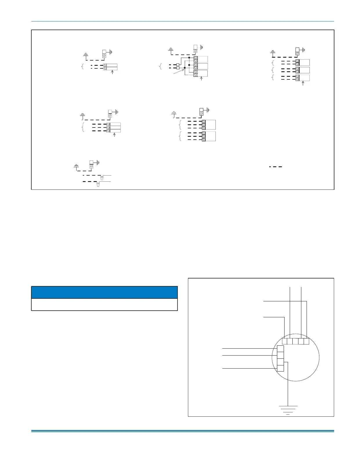
Figure 15: Line power connections
.
A1699-001
3
2
1
GND
SD
SD
SD
GND
GND
CKT
L1
L2
L1
L2
SD
SD
SD
CKT
CKT
2
1
L1
L2
L3
L1
L2
L3
L1
L2
L3
GND
CN
CN
CKT
CKT
SD
SD
GND
GND
L1
L2
L1
L2
L1
L2
Two circuits on 15 kW to 20 kW
Three circuits on 25 kW
Field power wiring
(208/230 V)
Component Codes:
GND - Ground lug
SD - Service disconnect
CKT - Circuit
CN - Wire connector/nut
1 Phase Electric Heat Power Options:
3 Phase Electric Heat Power Options:
Single source power
Power supply Power supply Power supply
Terminal block or service disconnect
Jumper bar
Two circuits on 15 kW to 20 kW
Three circuits on 25 kW
Multi-source power with jumper bar Multi-source power
No Electric Heat:
Power supply
Single source power Multi-source power
Power supply
Terminal block or service disconnect
Power supply
NOTICE
All wiring must comply with local and national electrical code require-
ments. Read and heed all unit caution labels.
Figure 16: Blower speed connections
GRN
Blower
motor
C
L
G
N
RED/WHT
BLK/WHT
BLU/WHT
RED
To resistor
YEL
BLK
Standard ECM - high efficiency motor
A1772-001
123 45
YEL/BLK
To 230 V on
transformer
To common
on transformer
To resistor