6112628-UIM-B-0622
12 Johnson Controls Ducted Systems
Section XII: Unit data
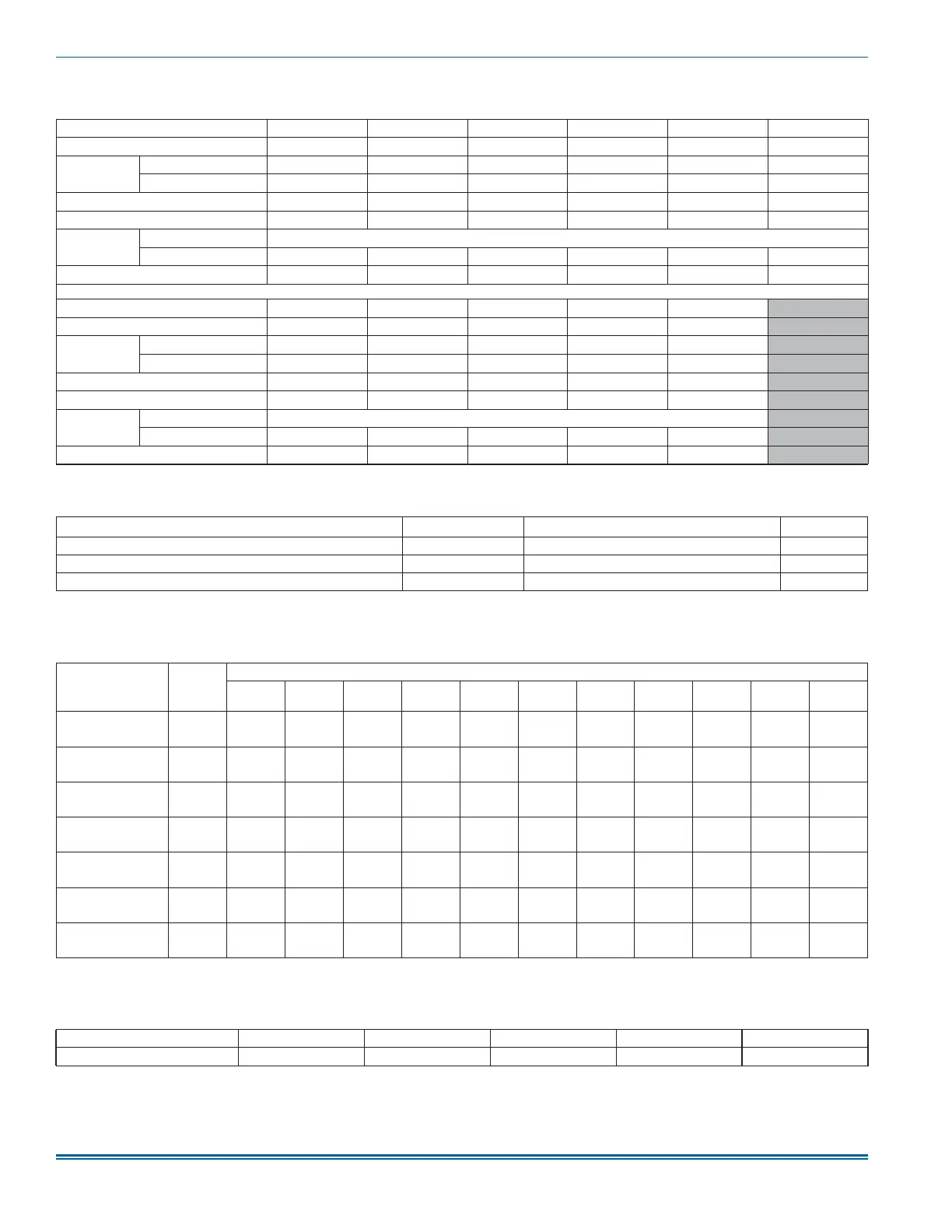
Table 3: Physical and electrical data - cooling only
Models B18B B24C B30D B36D C36D C42F
Blower - diameter x width (in.) 11 x 8 11 x 8 11 x 8 11 x 8 11 x 10 11 x 10
Motor
HP 1/3 HP 1/3 HP 1/2 HP 1/2 HP 1/2 HP 1/2 HP
Nominal RPM 1050 1050 1050 1050 1050 1050
Voltage (V) 208/230 208/230 208/230 208/230 208/230 208/230
Full load amps at 230 V (A) 2.6 2.6 3.8 3.8 3.8 3.8
Filter
1
Type Disposable or cleanable
Size (in.) 16 x 20 x 1 16 x 20 x 1 16 x 20 x 1 16 x 20 x 1 20 x 20 x 1 20 x 20 x 1
Shipping / operating weight (lb) 101/93 107 / 99 108 / 100 108 / 100 124 / 114 135 / 125
Models C48G D48G C60H D60H D60J
Blower - diameter x width (in.) 11 x 10 11 x 11 11 x 10 11 x 11 11 x 11
Motor
HP 3/4 HP 3/4 HP 3/4 HP 3/4 HP 3/4 HP
Nominal RPM 1050 1050 1050 1050 1050
Voltage (V) 208/230 208/230 208/230 208/230 208/230
Full load amps at 230 V (A) 5.4 5.4 5.4 5.4 5.4
Filter
1
Type Disposable or cleanable
Size (in.) 20 x 20 x 1 23 x 20 x 1 20 x 20 x 1 23 x 20 x 1 23 x 20 x 1
Shipping / operating weight (lb) 140 / 129 152 / 140 153 / 141 158 / 146 162 / 150
1. Field supplied.
Table 4: Electrical data - cooling only
Models
Motor FLA
1
Minimum circuit ampacity (A)
MOP
2
B18B/B24C 2.6 3.3 15
B30D/B36D/C36D/C42F 3.8 4.8 15
C48G/D48G/C60H/D60H/D60J 5.4 6.8 15
1. FLA = Full Load Amps
2. MOP = Maximum Overcurrent Protection device; must be HACR type circuit breaker or time delay fuse. Refer to the latest edition of the National Electric Code or in Canada the
Canadian electrical Code and local codes to determine correct wire sizing.
Table 5: Electrical heat: minimum fan speed
Heater kit
models
1,2
Nominal
kW
at 240 V
Air handler models
B18B B24C B30D B36D C36D C42F C48G D48G C60H D60H D60J
8HK(0,1)6500206
2.4
Medium
Low (2)
Medium
(3)
Medium
High (4)
Medium
(3)
Medium
(3)
Medium
(3)
Medium
Low (2)
Medium
Low (2)
Medium
Low (2)
Medium
Low (2)
Medium
Low (2)
8HK(0,1)6500506
4.8
Medium
(3)
Medium
(3)
Medium
High (4)
Medium
(3)
Medium
(3)
Medium
(3)
Medium
Low (2)
Medium
Low (2)
Medium
Low (2)
Medium
Low (2)
Medium
Low (2)
8HK(0,1)6500806
7.7
Medium
High (4)
Medium
High (4)
Medium
High (4)
Medium
High (4)
Medium
High (4)
Medium
High (4)
Medium
(3)
Medium
(3)
Medium
(3)
Medium
(3)
Medium
Low (2)
8HK(0,1)6501006
8HK06501025
9.6
Medium
High (4)
Medium
High (4)
Medium
High (4)
Medium
High (4)
Medium
High (4)
Medium
High (4)
Medium
(3)
Medium
(3)
Medium
High (4)
Medium
(3)
Medium
Low (2)
8HK(1,2)6501506
8HK06501525
14.4
—
Medium
High (4)
High (5)
Medium
High (4)
Medium
High (4)
Medium
High (4)
Medium
(3)
Medium
(3)
Medium
High (4)
Medium
High (4)
Medium
(3)
8HK(1,2)6502006
8HK16502025
19.2
— — High (5)
Medium
High (4)
High (5) High (5)
Medium
High (4)
Medium
(3)
Medium
High (4)
Medium
High (4)
Medium
(3)
8HK(1,2)6502506
8HK16502525
24
— — — — — — — — —
Medium
High (4)
Medium
(3)
1. (0,1) - 0 = no service disconnect or 1 = with service disconnect.
2. (1,2) - 1 = with service disconnect, no breaker jumper bar or 2 = with service disconnect and breaker jumper bar.
Table 6: Application factors - rated CFM versus actual CFM
% of rated airflow (CFM) 80 90 100 110 120
Capacity factor 0.96 0.98 1 1.02 1.03
 Loading...