6112628-UIM-B-0622
Johnson Controls Ducted Systems 7
Unit connections
There are several ways to handle the supply and return air duct connec-
tions. The location and sizing of the connections depends on the situa-
tion and the method best suited to the installation. Upflow, horizontal or
downflow applications may be used.
Use a transition to match unit opening to correctly size the supply air
duct. See Table 1 for air handler unit inlet and outlet dimensions.
Ductwork that is not designed to match the supply air opening can
cause turbulence inside the plenum. This turbulence can change the
airflow patterns across the electric heater limit switch/switches. If the
factory suggested transition cannot be fabricated, attach a block off
plate (approximately 8 in. high and running the full width of the plenum)
to the supply opening. See Figure 8. The use of this block off plate
enables better air circulation across the limit switches.
Air filters
.
Return air filters are required and must be field supplied. Filtration can
be accomplished external to the unit or the integral filter rack may be
used. A 1 in. filter access rack is built into the unit. Remove the filter
access cover and install the correct size filter. Use a standard 1 in. per-
manent or throw away filter. See Table 3 for filter sizes.
Section V: Coil metering devices
Install a piston or a TXV in the field. There is an installation manual that
comes with the TXV kit. Install the piston or TXV kit prior to brazing of
the refrigeration piping. Until brazing is completed and cooled, do not
install the TXV sensing bulb.
Consult the outdoor unit Technical Guide for the required piston or TXV
on the indoor coil. A piston and Schrader valve core are supplied with
the outdoor unit if applicable. When using a piston instead of a TXV,
install the Schrader valve core in the suction line equalizer connection
port and cap it with the supplied plastic cap. Do not install the Schrader
valve core if installing the TXV, because the TXV equalizer line attaches
to the equalizer connection port.
Piston installation
Install the Schrader valve core and piston as follows:
1. After discharging the holding charge completely, remove the black
plastic cap from the equalizer connection port on the vertical part
of the vapor line.
2. Adjust the distributor position to allow the preformed liquid line
assembly to properly line up with the hole in the tubing access
panel. Raise the distributor body approximately 2 in. toward the top
of the coil or what would be the top of the coil if the coil was in the
upflow position. See Figure 9 and adjust as necessary.
3. Install the Schrader valve core supplied with the outdoor unit into
the equalizer fitting connection port using a valve core tool.
4. Loosen and remove the liquid line connection nut and the sealing
disc from the distributor assembly. Note that the fitting has right
hand threads.
5. Slide the nut over the liquid line and discard the seal disc.
6. Install the required size piston into the distributor. Refer to the Tabu-
lar Data Sheet for the specific piston size and indoor coil match up.
See Figure 10.
7. Verify that the PTFE washer is still in place in the distributor open-
ing. See Figure 10.
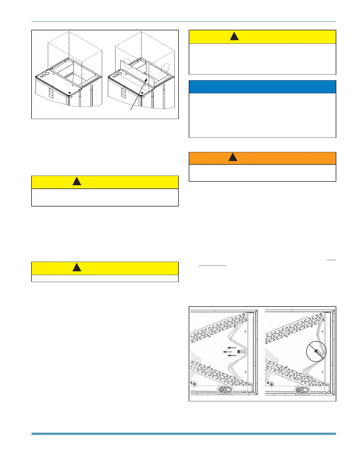
Figure 8: Ductwork transition
CAUTION
Use 1/2 in. screws to connect ductwork to the unit. Longer screws
may pierce the drain pan and cause leakage. If drilling pilot holes, drill
only though the field duct and the unit bottom duct flange.
CAUTION
Never operate the equipment without filters.
A1697-001
Suggested location of block off plateRecommended transition
!
!
CAUTION
COIL UNDER PRESSURE.
Verify that pressure has been released by depressing the Schrader
valve core shown in Figure 2.
The coil requires a metering device to be added. Refer to outdoor unit
documentation for the correct TXV or piston to use.
NOTICE
To prevent moisture and contaminates from entering the system, the
coil must not be open to atmosphere for extended periods of time. If
the coil cannot be brazed into the refrigeration system during a rou-
tine installation period, the ends must be temporarily closed or
plugged. For a short term delay, use masking tape over the ends of
the copper tubing to close the tube from the air. For a longer term
delay, use plugs or caps. There is no need to purge the coil if this pro-
cedure is followed.
WARNING
Failure to install a Schrader valve core in the vapor line equalizer con-
nection port for piston applications could result in total refrigerant loss
of the system.
Figure 9: Recommended distributor adjustment
!
!
A1670-001