6112628-UIM-B-0622
10 Johnson Controls Ducted Systems
Section VII: Condensate drain connections
Adhere to the following:
• Pitch all drain lines 1/4 in./ft away from the unit drain pan and
make sure that the drain lines are no smaller than the coil drain
connection.
• Route the drain line so that it does not impede access to the coil,
air handling system, or filter and is not exposed to freezing tem-
peratures.
• Instruct the homeowner that the indoor coil drain pan must be
inspected and cleaned regularly to prevent odors and ensure
proper drainage.
• Install the air handling unit pitched slightly toward the drain end.
• Note that you can remove drain plugs using a standard 3/8 in.
drive socket ratchet.
• If the coil has a secondary drain, pipe it to a location that gives
the occupant a visual warning that the primary drain is clogged. If
a secondary drain is not used, you must plug the secondary
drain.
Section VIII: Electric heater installation
If the air handler requires electric heat, install the electric heat kit
according to the installation instructions included with the kit. After
installing the kit, mark the air handler nameplate to designate the heater
kit that was installed. If no heater is installed, mark the name plate
appropriately to indicate that no heat kit is installed.
Use only 8HK heater kits, as listed on the air handler name plate and in
these instructions. Use data from Table 5 to Table 12 for information on
the required minimum motor speed tap to use for heating operation and
the maximum over-current protection device required as listed for com-
bination of air handler and heater kit.
Section IX: Line power connections
Power can be brought into the unit through the supply air end of the unit
(top left when unit is vertical) or the left side panel. Use the hole appro-
priate to the unit’s orientation in each installation to bring the conduit
from the disconnect. The power lead conduit must be terminated at the
electrical control box. See Table 8 to Table 12 and the latest edition of
the National Electric Code, or in Canada the Canadian electrical Code,
and local codes to determine correct wire sizing. To minimize air leak-
age, seal the wiring entry point on the outside of the unit.
All electrical connections to air handlers must be made with copper con-
ductors. Direct connection of aluminum wiring to air handlers is
not approved.
If aluminum conductors are present, all applicable local and national
codes must be followed when converting from aluminum to copper con-
ductors prior to connection to the air handler.
The chosen conductor and connections must all meet or exceed the
amperage rating of the overcurrent protector (service disconnect or
fuse) in the circuit.
Existing aluminum wire within the structure must be sized correctly for
the application according to the National Electric Code and local codes.
Use caution when sizing aluminum rather than copper conductors, as
aluminum conductors are rated for less current than copper conductors
of the same size.
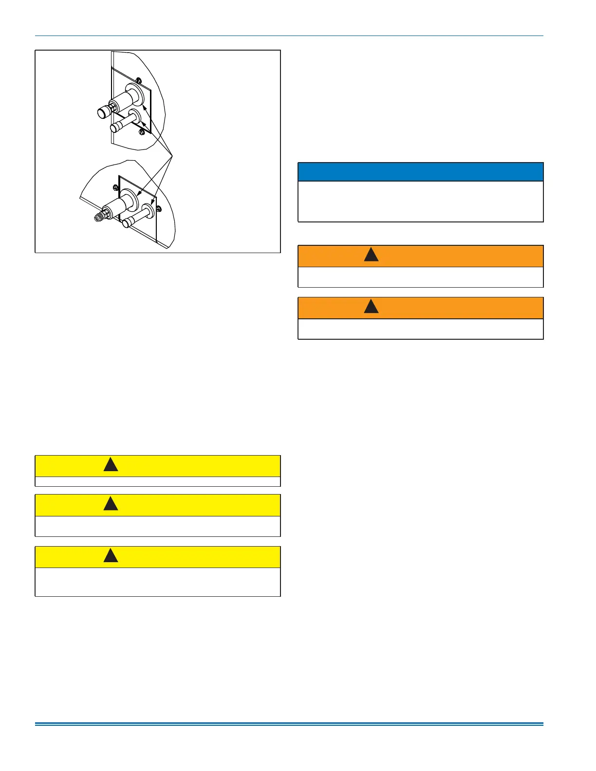
Figure 14: Grommets
CAUTION
Avoid double trapping.
CAUTION
Threaded drain connections must be hand tightened, plus no more
than one turn.
CAUTION
Do not use PTFE tape, pipe thread compound, or other sealants. Use
of a sealant can cause damage and premature failure of the drain
pan.
A1669-003
Grommets
!
!
!
NOTICE
In some horizontal applications, the service disconnects on the elec-
tric heat kits must be rotated 180° so the up position of the discon-
nect is the ON position. This service disconnect orientation change is
required by UL 60335-2-40 (in reference to all circuit breakers).
WARNING
Before obtaining access to terminals, all supply circuits must be dis-
connected.
WARNING
A fused disconnect switch must be field provided for the unit to be in
compliance with UL 60335-2-40 Clause 7.12.2.
!
!