6112628-UIM-B-0622
4 Johnson Controls Ducted Systems
Section III: Unit installation
Unit sizing
1. The size of the unit must be based on an acceptable heat loss or
gain calculation for the structure. Use Air Conditioning Contractors
of America (ACCA) Manual J or another approved method.
2. Only connect the air handler to a duct system that has an external
static pressure within the allowable range.
3. Airflow must be within the minimum and maximum limits approved
for electric heat, indoor coils, and outdoor units.
4. When an air handler is installed so that supply ducts carry air circu-
lated by the air handler to areas outside the space containing the air
handler, the return air is also handled by one or more ducts sealed
to the air handler casing and terminating in the space to be cooled
or heated.
5. Refer to the unit rating plate for the air handler model number and
then see the dimensions page of this manual for supply air plenum
dimensions. The plenum must be installed according to the instruc-
tions.
6. The installer must check available supply power and verify that it is
within the normal operating voltage range for the unit. The accept-
able voltage range for these units is as follows:
Clearances
It is essential to provide the following clearances:
1. Refrigerant piping and connections - minimum 12 in.
2. Maintenance and servicing access - minimum 36 in. from the front
of the unit for blower motor or coil replacement
3. Condensate drain lines routed to clear filter and panel access
4. Filter removal - minimum 36 in.
5. The supply air ductwork connected to this unit is designed for 1 in.
clearance for the first 18 in. of combustible materials if an electric
heat kit accessory is installed.
6. A combustible floor base accessory is available for downflow appli-
cations of this unit, if required by local code.
Location
Location is usually predetermined. Check with the owner’s or dealer’s
installation plans. If location has not been decided, consider the follow-
ing in choosing a suitable location:
1. Select a location with adequate structural support, space for service
access, and clearance for air return and supply duct connections.
2. Do not use hanging brackets to wall mount this single piece air han-
dler unit.
3. Normal operating sound levels may be objectionable if the air han-
dler is placed directly over some rooms such as bedrooms or a
study.
4. Select a location that permits installation of the condensate line to
an open drain or outdoors, allowing condensate to drain away from
the structure.
5. When installing an indoor coil in an attic or above a finished ceiling,
an auxiliary drain pan must be provided under the air handler as is
specified by most local building codes.
6. A sufficient electrical supply must be available.
7. If locating the unit in an area of high humidity, such as an uncondi-
tioned garage or attic, nuisance sweating of the casing may occur.
On these installations, completely seal the unit duct connections
and other openings, and use a wrap of 2 in. fiberglass insulation
with vinyl vapor barrier.
Air handler configuration
These air handler units are supplied ready to install in an upflow or hor-
izontal left position. See Figure 4. If the unit requires either downflow or
horizontal right airflow configurations, the unit must have the coil
assembly repositioned. See Downflow or horizontal right conversion.
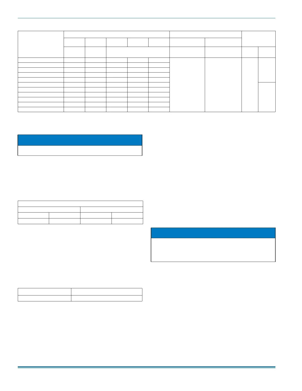
Table 1: Dimensions
1
Models
Dimensions
Wiring knockouts
2
Refrigerant
connections
line size
A B C D E F G
Height
(in.)
Width (in.) Opening widths (in.) Power (in.) Control (in.)
Liquid
(in.)
Vapor
(in.)
JHETB18B 47 17 1/2 7 1/2 16 1/2 16 1/2
7/8 (1/2)
1 3/8 (1)
1 23/32 (1 1/4)
7/8 (1/2) 3/8
3/4
JHETB24C 49 5/8 17 1/2 10 16 1/2 16 1/2
JHETB30D 49 5/8 17 1/2 10 16 1/2 16 1/2
JHETB36D 49 5/8 17 1/2 10 16 1/2 16 1/2
JHETC36D 51 21 11 1/2 20 20
JHETC42F 57 21 17 1/2 20 20
7/8
JHETC48G 61 1/4 21 21 3/4 20 20
JHETD48G 61 1/4 24 1/2 21 3/4 23 1/2 23 1/2
JHETC60H 63 21 23 1/2 20 20
JHETD60H 63 24 1/2 23 1/2 23 1/2 23 1/2
JHETD60J 61 1/4 24 1/2 21 3/4 23 1/2 23 1/2
1. All dimensions are in inches.
2. Actual size (conduit size).
NOTICE
Avoid handling aluminum coil components after handling the copper
refrigeration piping or other tubing without first cleaning hands.
Entering air temperature limits
Wet bulb temperature (°F) Dry bulb temperature (°F)
Minimum Maximum Minimum Maximum
57 72 65 95
Air handler voltage
Normal operating
1
voltage range
1. Rated in accordance with ARI Standard 110, utilization range A.
208/230-1-60 187 V to 253 V
NOTICE
The primary and secondary drain line must be trapped to allow proper
drainage of condensate water. The secondary drain line must be
piped to a location that gives the occupant a visual warning that the
primary drain is clogged. If the secondary drain line is not used, it
must be capped.