6112628-UIM-B-0622
8 Johnson Controls Ducted Systems
8. After the piston is installed, install the liquid line to the top of the pis-
ton/distributor assembly. Hand tighten and turn an additional 1/4
turn to seal.
Do not over tighten fittings.
9. Replace the black plastic cap on the unused equalizer fitting con-
nection port.
10. After installing the refrigeration piping, leak test the system.
Thermal expansion valve (TXV) installation
The following are basic steps for installation. For detailed instructions,
refer to the Installation Manual accompanying the TXV kit. Complete
the following steps to install the TXV kit:
1. Relieve the holding charge by depressing the Schrader valve core
on the suction manifold stub out.
2. After discharging the holding charge completely, loosen and
remove the Schrader valve core.
3. Place a backup wrench on the distributor, then loosen and remove
the brass distributor nut. Retain the brass nut for use on the liquid
line. Keep the PTFE washer in place and discard the seal disk.
4. Install the thermal expansion valve into the distributor assembly
with the supplied fittings. Ensure the PTFE washer is seated in the
distributor. Hand tighten and turn an additional 1/4 turn to seal. Do
not over-tighten fittings. See Figure 11.
5. Slide the nut removed in Step 3 over the supplied liquid line. Place
the supplied PTFE washer from the TXV kit in place on the TXV
and install the liquid line into the top of the thermal expansion valve.
Adjust the assembly so the liquid line aligns with the hole in the
access panel. See Figure 12. Hand tighten the liquid line and apply
an additional 1/4 turn to seal.
6. Install the TXV equalizer line onto the vapor line by hand tightening
the 1/4 in. SAE coupling nut to the equalizer fitting and apply an
additional 1/3 turn to seal. See Figure 12.
7. Route the temperature sensing bulb tube for the TXV toward the
vapor line header and the TXV equalizer tube connection port on
the vapor line header.
8. Install the TXV bulb to the vapor line near the TXV equalizer tube
connection port, using the bulb clamps supplied with the TXV
assembly. Ensure the bulb makes maximum contact. See Figure
12 and Figure 13, and complete the following steps:
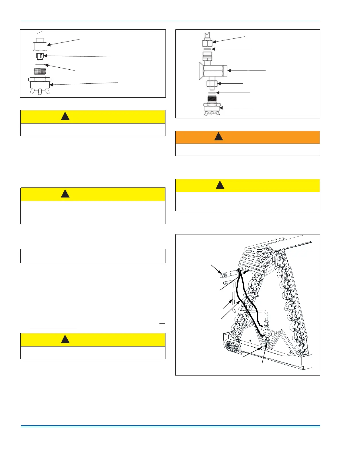
Figure 10: Piston installation
CAUTION
Do not overtorque. Do not use slip joint pliers. This will distort the alu-
minum distributor and the brass fitting (potentially causing leaks).
CAUTION
Outdoor unit model numbers ending with an H have a factory installed
hard start kit which is required when a TXV is installed. Outdoor unit
model numbers with no H ending do not require a hard start kit unless
the outdoor unit Data Sheet indicates it.
Important: Refer to the Technical Guide or Data Sheet for the unit to
determine the correct TXV kit to use on this product.
CAUTION
Do not overtorque. Do not use slip joint pliers. This will distort the alu-
minum distributor and the brass fitting (potentially causing leaks).
A0305-003
Distributor
Piston
Liquid line swivel coupling
(This ¿WWLQJLVDULJKWKDQGHGWKUHDG
TXUQFRXQWHUFORFNZLVHWRUHPRYH
PTFE ZDVKHU
!
!
!
Figure 11: TXV installation
WARNING
The Schrader valve core must not be installed with TXV installation.
Poor system performance or system failure could result.
CAUTION
In all cases, mount the TXV temperature sensing bulb after the vapor
line is brazed and sufficiently cooled.
Failure to use a suction line split grommet may result in TXV failure.
Figure 12: TXV bulb and equalizer line installations
A0281-004
TXV/distributor coupling
Liquid line/TXV coupling
PTFE washer
TXV
PTFE washer
Distributor
!
!
Indoor coil header assembly
(header body)
TXV bulb
(wrap with
insulation)
Liquid line
TXV equalizer line
Distributor body
Thermal expansion valve (TXV)
A1671-001