Wiring the communicator to the DSC PowerSeries alarm
panels
• Recommended location and wiring methods must be in accordance with the National Electrical
code, ANSI/NFPA 70.
• The communicator must be powered by a control panel.
• The system should be tested once per week.
• The wiring should be done only when the panel is powered down.
• For dry/indoor use only.
The LE4050M communicator is equipped with 2 Terminals for power supply and a 5 PIN connector
that should be wired and mounted into the box of the DSC PowerSeries alarm panel.
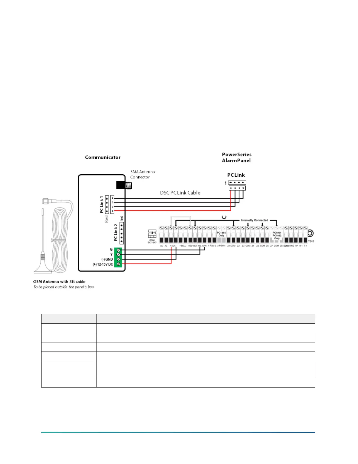
Figure 3: Wiring diagram for DSC PowerSeries alarm panels
Callout Description
(+) Connect this terminal to AUX + of the DSC PowerSeries alarm panel
(-) Connect this terminal to AUX – (GND) of the DSC PowerSeries alarm panel
G Connect this terminal to GRN of the DSC PowerSeries alarm panel.
Y Connect this terminal to YEL of the DSC PowerSeries alarm panel.
PC link 1 Connect this terminal to PC Link terminal of the DSC PowerSeries Panel via
DSC PC Link Cable
PC link 2 Not used
LE4050M INSTALLATION MANUAL12