Mounting the communicator
This communicator comes together with 4-PIN and additional 1-PIN serial cable, external antenna,
and mounting standoffs.
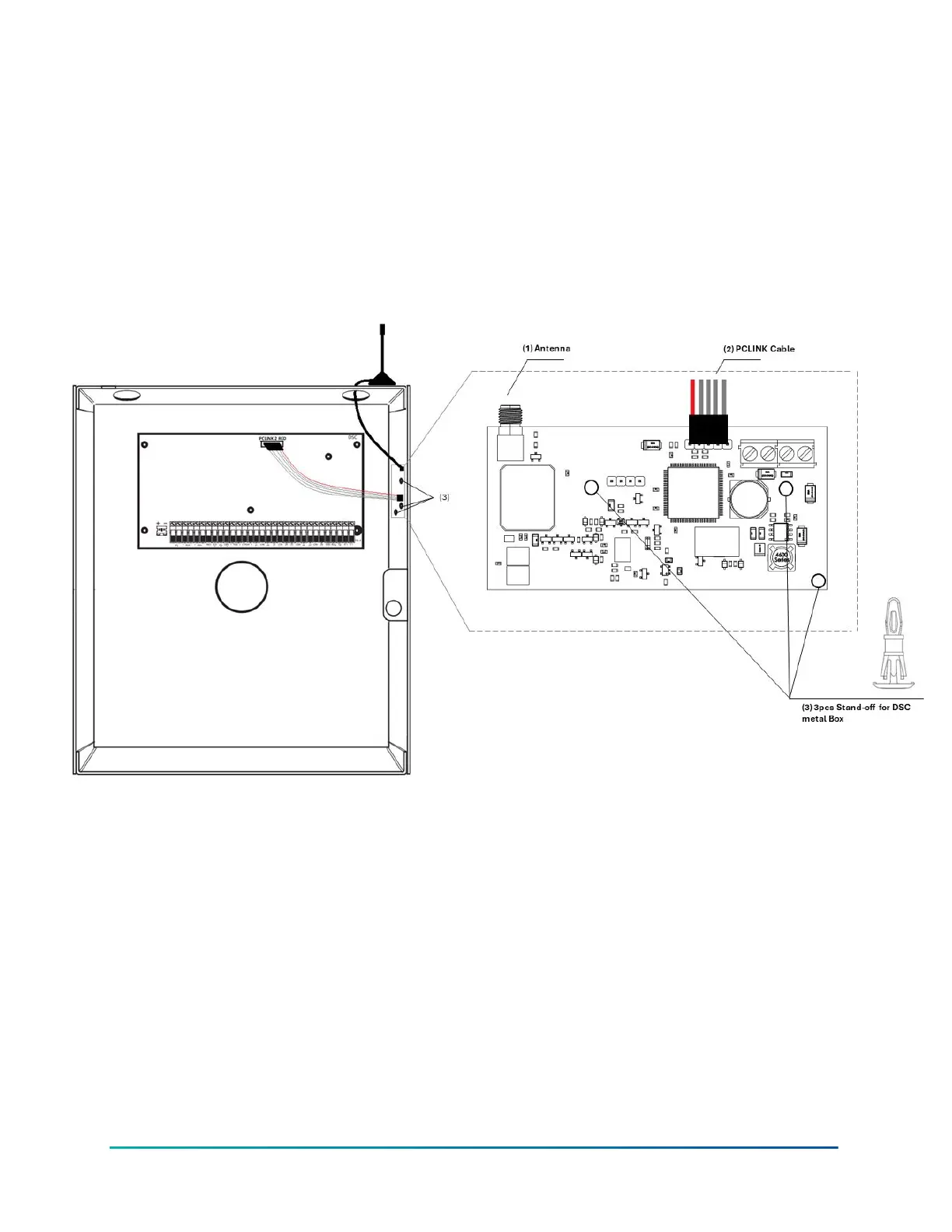
The device must be installed within a DSC PowerSeries/ PowerSeries NEO metal enclosure. The
communicator has mounting openings matching the panel openings. The mounting is done via
plastic standoffs, provided with the communicator. The antenna must be installed on top of the
enclosure, removing one of the knockouts, as per the installation instructions.
Figure 4: Mounting the communicator
1. Mo
unt the communicator using the provided plastic standoffs as shown in Figure 3 above.
2. Connect the antenna to the communicator. The antenna is supplied with SMA connector, that
allows easy connection to the communicator. The body of the antenna has a magnet bottom
and can be attached to the wall of the metal alarm panel box or use double sided adhesive type
to securely attach the antenna to the box. The antenna should be positioned perpendicular to
the ground, either right side up or upside down. Try to keep the antenna away from sources
of RF interference or where metal objects can shield it or otherwise block the cellular radio RF
signal.
3. Wire the communicator to the alarm panel – refer to the wiring sections of this manual.
4. Power up the panel.
LE4050M INSTALLATION MANUAL14