LN Application Specific, Remote I/O, and Free Programmable Controllers Installation Instructions
3
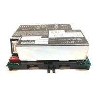
Mounting
You can mount each controller on a DIN rail, on a wall, or in a panel. The controllers are equipped with two
mounting holes 0.25 x 0.165 in. (6.36 x 4.191 mm).
Location Considerations
Observe these guidelines when mounting an LN Application Specific or Remote I/O Module:
• Provide for sufficient space around the device for cable and wire connections, access to service pin, hardware
configuration, maintenance, easy cover removal, and good ventilation.
• Ensure proper ventilation of each device and avoid areas where corroding, deteriorating, or explosive vapors,
fumes, or gases may be present.
• Orient each controller with the ventilation slots and power supply/output terminal block connector towards the
top to permit proper heat dissipation.
• Do not mount the controller on surfaces prone to vibration, such as duct work, or in areas where
electromagnetic emissions from other devices or wiring can interfere with communication.
DIN Rail
To mount the controller on a DIN rail:
1. Ensure the DIN rail is properly mounted on the wall.
2. Clip the controller onto the DIN rail.
Wall Mount
To mount the device on a wall:
1. Press on the side clips to separate the device’s front and back plates.
2. Use the holes on the back plate to mark the wall location.
3. Drill the holes.
4. Clean the surface and mount the unit using the appropriate screws.
 Loading...