LN Application Specific, Remote I/O, and Free Programmable Controllers Installation Instructions
12
Strain Relief and Terminal Block Cover
In certain jurisdictions, terminal block covers are required to meet local safety regulations. Strain reliefs and
terminal block covers are available for controllers housed in the large enclosures and are used to relieve tension on
the wiring and conceal the controllers' wire terminals. Strain reliefs and terminal block covers are optional and are
sold separately.
Prior to connecting all wires, it is recommended that you install the strain relief. Three screws are provided for its
installation under the bottom part of the enclosure. You can then use tie wraps to group wires together and attach
them securely to the strain relief in an effort to relieve undue tension. If necessary, clip the terminal block cover to
the strain relief as shown in Figure 21.
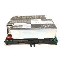
Figure 21: Large Enclosure Strain Relief and
Terminal Block Cover Installation
 Loading...