4 M9106-xGx-2 Series Electric Non-Spring Return Actuators Installation Instructions
GGx Models
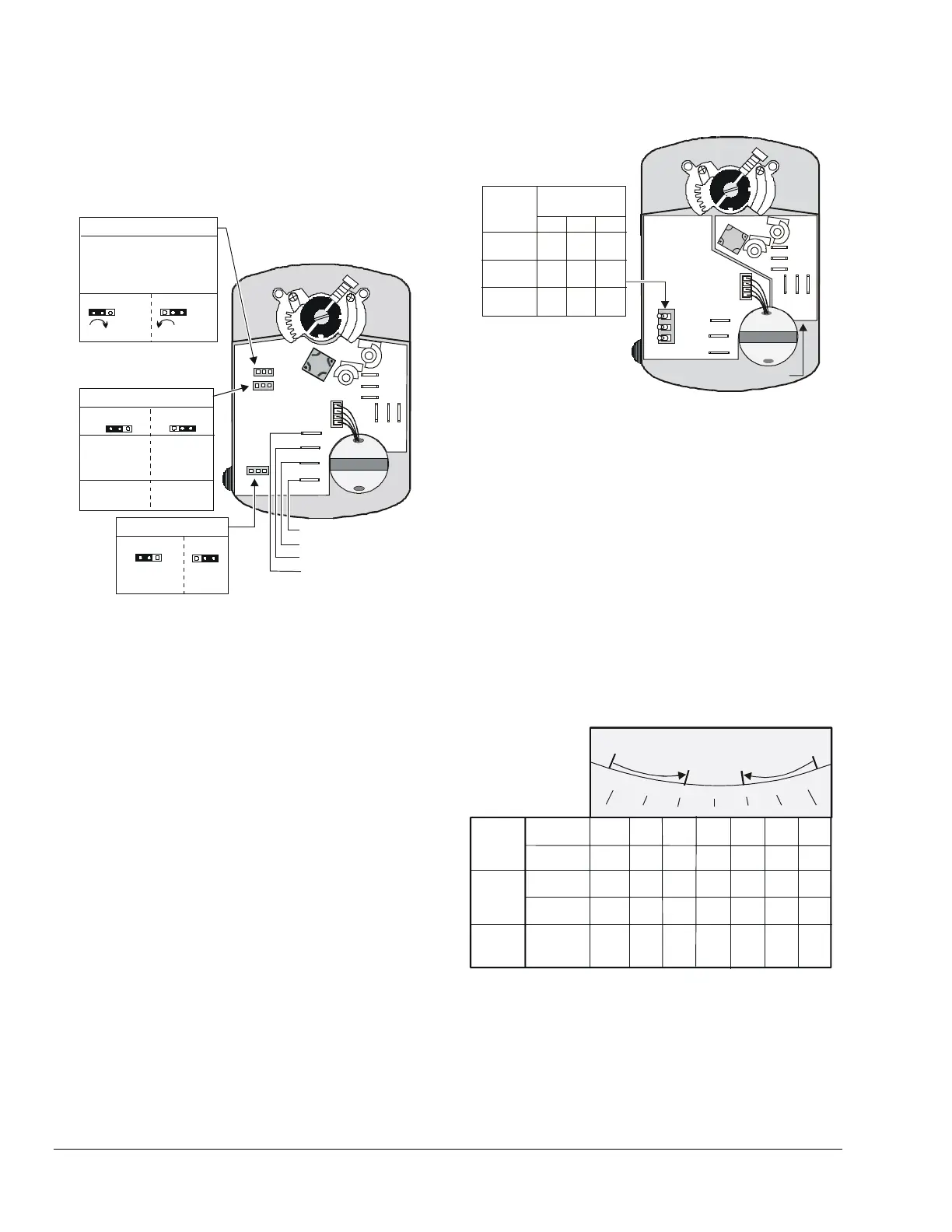
The M9106-GGx-2 proportional actuators are
factory set for Direct Acting (DA) mode with
Jumper W1 in the DA position. Remove Jumper W1
and place it in the RA position. (See Figure 7.)
(CW) DA
(CCW) RA
NC2
NO2
C2
C1
NC1
NO1
FB
VDC/mA
+24
COM
Jumper W3
Factory Set
VDC mA
Jumper W2
Jumper W1
Factory Set
Input
Input
0-10 VDC
0-20 mA
2-10 VDC
4-20 mA
Feedback
0-10 VDC
2-10 VDC
Direct Acting (DA)
Reverse Acting (RA)
Rotation Direction
with Increasing Signal
Factory Set
Note: Jumper W1 is not
available on the
floating models.
Common
+24 VAC Power
VDC/mA
Feedback Output
Figure 7: Calibrating the GGx Models
Jumpers (GGx Models)
The M9106-GGx-2 proportional actuators are
factory set with Jumper W2 in the 0 to 10 VDC position
and Jumper W3 in the VDC position.
The VDC/mA terminal is the control input signal.
Jumper W3 must be in the VDC position for
voltage input and in the mA position for current input.
The FB Terminal is the feedback output. (See
Figure 7.)
Mode Switches (IGx Models)
The M9106-IGx-2 models offer adjustable rotation
times of 1, 1.5, 2, 5.5, and 11 minutes (factory set for
1 minute). Switch settings determine the rotation time
of the IGx models. Refer to Figure 8 to position the
mode switches for the desired rotation time.
NC2
NO2
C2
C
1
N
C
1
N
O
1
Time
(Minutes)
1.0
1.5
2.0
5.5
11.0
1.0
Off
On
Off
On
Off
On
A
B
C
Off
Off
Off
Off
Off
Off
On
Off
On
On
On
On
Mode
Switch Settings
A
B
C
Note: The IGA models have Board 1, and the IGC models
have both Board 1 and Board 2.
Board 1
Board 2
COM
CW
CCW
Off On
Figure 8: Mode Switch Settings on IGx Models
The 1-, 1.5-, and 2-minute settings are ideal for on/off
and floating applications, and replace the
M9104-xGx-2 1.5-minute models. The 5.5- and
11-minute settings are replacements for the 35 lb∙in
(4 N∙m) EDA-2040 and the ATP-2040 models.
Feedback Signal
The feedback signal will vary with a change to the
rotation range. For the GGA and GGC models, a
change to the rotation range changes the feedback
signal and the operating range proportionally. For the
AGF model, resistance feedback is reduced
corresponding to the reduced rotation range. (See
Figure 9.)
90°
90°
0.0V
2.0V
10.0V
8.7V
7.3V
6.0V
4.7V
3.3V
10.0V
8.3V
6.7V
5.0V
3.3V
1.7V
75°
75°
60°
60°
45°
45°
30°
30°
15°
15°
0°
0°
Rotation Range
2-10V
Feedback
0-10V
Feedback
Direct
Acting
10.0k
Ω
6.7k
Ω
1.7k
Ω
Ω
0
8.3k
Ω
0-10k ohms
Feedback
Ω
5.0k
3.3k
Ω
Direct or
Reverse
Acting
2-10V
Feedback
Reverse
Acting
0-10V
Feedback
0.0V
1.7V
3.3V 5.0V
6.7V
8.3V
10.0V
10.0V
8.7V7.3V
6.0V4.7V
3.3V
2.0V
Set Screw
Adjustment
Set Screw
Adjustment
Note:
0-10k ohms feedback is available on AGF models.
0-10V is available on GGA and GGC models.
Figure 9: Nominal Feedback Signal Relative to
the Rotation Range

 Loading...


