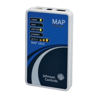
Although the bracket has two mounting clips, only the
bottom clip snaps inward. The top clip is permanently
locked in the outward position, and it can be used as an
additional hole for screwing the bracket into place. If not
utilized for DIN rail or surface mounting, the top and
bottom clips may be removed from the mounting bracket.
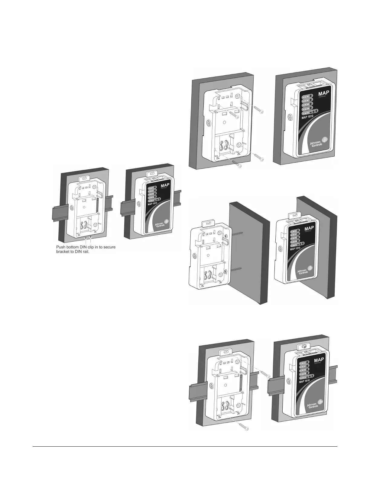
DIN Rail Mounting
To mount the bracket on a DIN rail:
1. Securely mount a 7.5 cm (3 in.) or longer section of
35 mm (1-1/8 in.) DIN rail in the required space.
2. On the bracket, pull the bottom mounting clip outward
to the extended position.
Figure 3: Positioning the Bracket on a DIN Rail
3. Hang the bracket on the DIN rail by the hooks at the
top of the DIN rail channel (on the back of the
bracket), and position the bracket snugly against the
DIN rail.
4. Push the bottom mounting clip inward to secure the
mounting bracket on the DIN rail.
5. Place the MAP Gateway unit in the bracket and
secure it with the locking screw.
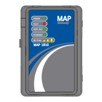
Wall Mounting
The bracket may be mounted using screw holes on the
back of the bracket (so that the unit is flat on its back),
using the screw holes on the side of the bracket, or using
the holes in the DIN rail clips. This orientation helps
accommodate on-site constraints. Screw hole locations
are illustrated in Figure 7, Figure 8, and Figure 9.
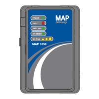
The screw types needed to mount the unit depend upon
the surface to which the unit is mounted. The screw holes
on the MAP Gateway can accommodate M3.5 and #6
screws.
For information on location considerations for maximizing
signal strength, see the Mounting section.
Figure 4: Sample Permanent Mounting, Back-side
Screws
Figure 5: Sample Permanent Mounting, Side Screws
Figure 6: Sample Permanent Mounting, DIN Rail
Screw Holes
4Mobile Access Portal Gateway Installation Instructions