CKM-MR52-S3 Hardware Installation Manual
24-10707-198 Rev. –
10
Run Time
1
(continued)
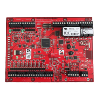
1 LED: Input Status: IN1
2 LED: Input Status: IN2
3 LED: Input Status: IN3
4 LED: Input Status: IN4
5 LED: Input Status: IN5
6 LED: Input Status: IN6
7 LED: Input Status: IN7
8 LED: Input Status: IN8
TMP: Cabinet Tamper
PFL: Power Fault
Input in the inactive state: OFF (briefly flashes ON every 3 seconds)
Input in the active state: ON (briefly flashes OFF every 3 seconds)
Input in a trouble state: Rapid Flash
R1 LED: reader port 1:
Clock/Data Mode: Flashes when data is received, either input
Data 0/Data 1 Mode: Flashes when data is received, either input
RS-485 Mode: Flashes when transmitting data
R2 LED: reader port 2:
Clock/Data Mode: Flashes when data is received, either input
Data 0/Data 1 Mode: Flashes when data is received, either input
RS-485 Mode: Flashes when transmitting data
K1 through K6 LEDs: Illuminates when output relay RLY 1 (K1) through
RLY 6 (K6) is energized.
1. Every 3 seconds, LEDs A through R2 are pulsed to their opposite state for 0.1 sec.
Table 3: LED Information
Process LED Information

 Loading...


