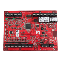
CKM-MR52-S3 Hardware Installation Manual
24-10707-198 Rev. –
9
STATUS LEDS
Table 2: Jumpers
Jumper Description
J1 Reader Power Select
12V = 12 VDC at reader ports.
1
1. The input power (VIN) must be 20 VDC minimum if the 12 VDC selection is to be used.
PT = VIN “Passed Through” to reader ports
J4 RS-485 Termination, install in first and last units only.
All other jumpers are for factory use only.
Table 3: LED Information
Process LED Information
Power-up All LEDs OFF
Initialization Once you apply power, initialization of the module begins.
When initialization is completed, LEDs A through R2 are briefly
sequenced ON then OFF.
Run Time
1
A LED Heartbeat and On-Line Status:
Offline
1-second rate, 20% ON
Online
Non-encrypted communication: 1-second rate, 80% ON
Encrypted communication:
0.1 second ON
0.1 second OFF
0.1 second ON
0.1 second OFF
0.1 second ON
0.1 second OFF
0.1 second ON
0.3 second OFF
A LED Error Indication:
Waiting for application firmware to be downloaded:
1 second ON
1 second OFF
B LED SIO Communication Port Status:
Indicates communication activity on the SIO communication port.

 Loading...


