CKM-MR52-S3 Hardware Installation Manual
24-10707-198 Rev. –
5
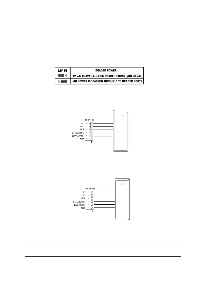
To fully utilize each reader port:
• TTL signaling requires a 6-conductor cable (18 AWG)
• RS-485 signaling requires two 2-conductor cables. Use one cable for
power (18 AWG) and one cable for communication (24 AWG, with
drain wire and shield).
Figure 4: J1 - Reader Port Power Select
Figure 5: Typical D1/D0 - Clock/Data Reader
Figure 6: Typical 2-Wire RS-485 Device
NOTE: If the input voltage to the MR52 is 12 VDC, jumper J1 must be in the PT
position.

 Loading...