Network Control Module 300 Series Technical Bulletin 38
DCD
1
2
3
4
5
6
7
8
9
2
3
4
5
6
7
8
11
20
NCM
9-pin Female
PRN-5
Connector
RD
NC
prn2nctc
In
In
In
In
Out
Out
Out
In
Out
Out
Out
In
In
TD
TD
RD
DTR
DSR
SG
SG
DSR
READY
CTS
RTS
CTS
RTS
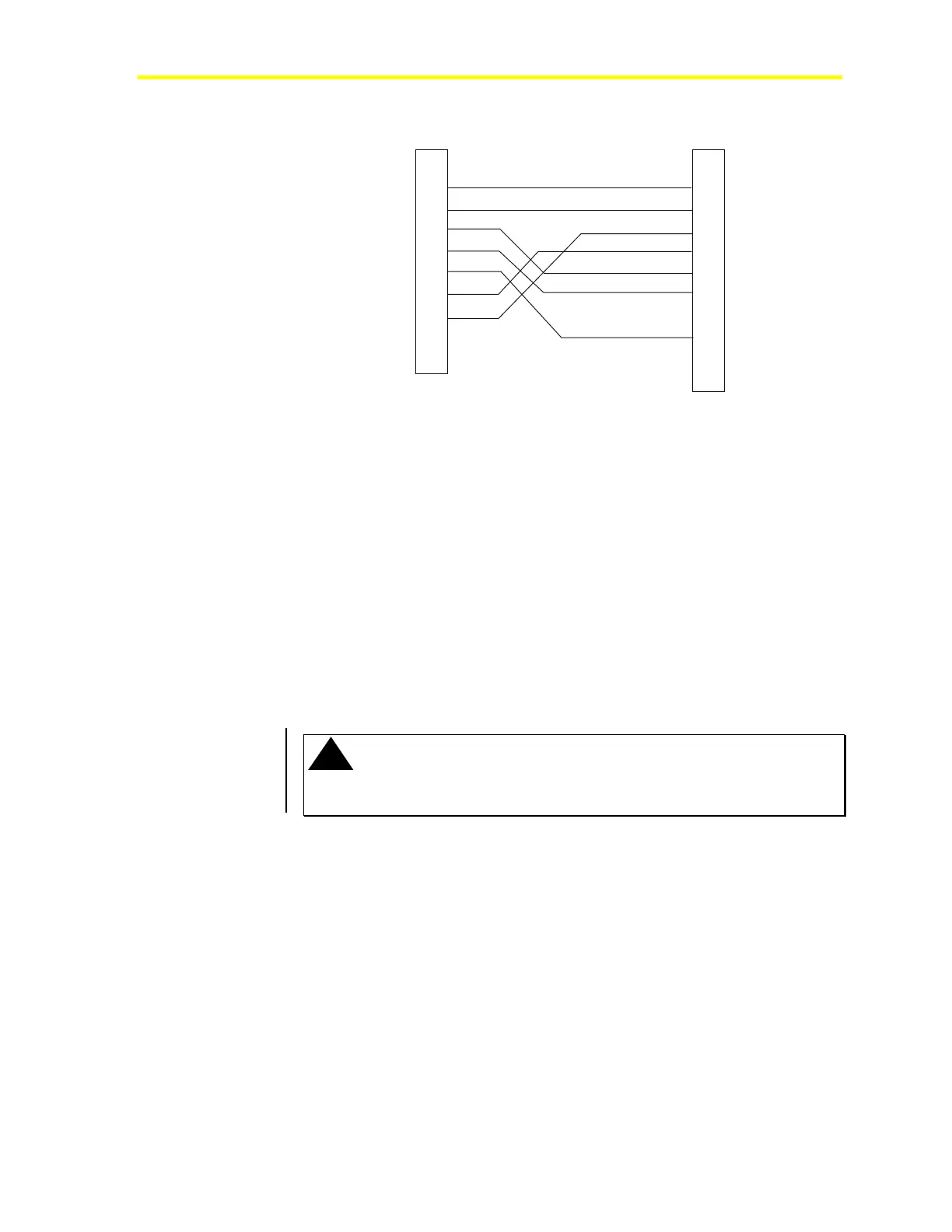
Figure 13: UL UUKL Smoke Control PRN-5 Connected to Port 2 or 3 of
the NCM
Network Terminal Cabling
Port 4 is composed of two connections (RJ-12 and DB9) leading to the
same circuit. Only one connection can be occupied at one time. The
RJ-12 connector, a 6-pin telephone jack, supports Transmit, Receive,
and Data Set Ready lines. This connection accepts either the NT cable
for connection to the NT or the NT Emulator cable for connection to
the NT Emulator or Operator Terminal (OT). The RJ-12 port does not
support the Zone Bus Terminal. Figure 14 shows the NT Emulator
cable for connecting the NT Emulator or OT to the RJ-12 connector
(Port 4). (The 9
to 25-pin converter cable is necessary if the PC has a
9-pin serial port.)
!
IMPORTANT: Do not plug a telephone line into the NT RJ-12 port.
Inserting a telephone line plug into the RJ-12 port may damage the NT port
and render it unusable.