Network Control Module 300 Series Technical Bulletin 44
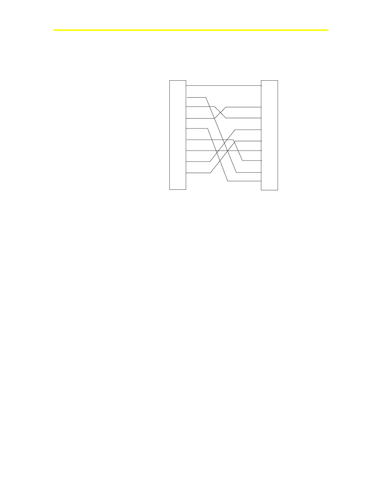
Cable connections from the TTM101, TTM102, and TTM103 to the
S2 NCM Port 2 require the following cable:
1
2
3
4
5
6
7
8
9
DCD
RXD
TXD
DTR
GND
DSR
RTS
CTS
NC
NCM
9-pin Female
2
3
4
5
6
7
8
20
S2 (TTM)
25-pin Male
Shell Shell
In
In
In
In
Out
Out
Out
In
In
Out
Out
Out
In
Out
nc3fig17
Figure 20: Table Top Modems to Port 2 of the S2 NCM
Software Setup
Several components integrate software and hardware into a system.
• The Software Architecture Technical Bulletin (LIT-636010)
provides an overall guide to objects and attributes.
• NCSETUP for Windows operating system, described in the
NCSETUP for Windows Technical Bulletin (LIT-6360251d),
establishes the NCM’s configuration and parameters in the
non-volatile RAM. This information sets the archive data path, the
port designations and values, the program set downloaded to the
NCM, dial-up phone numbers when applicable, and other
parameters.
• The NCM Definition window (Figure 21) identifies the NCM to
the system. The process also correlates non-volatile RAM
parameters, maps, associated graphics, and help screens to the
defined NCM. The Operator Workstation User’s Manual describes
how to define hardware objects.