Network Control Module 300 Series Technical Bulletin 42
Gateway Migration Cabling
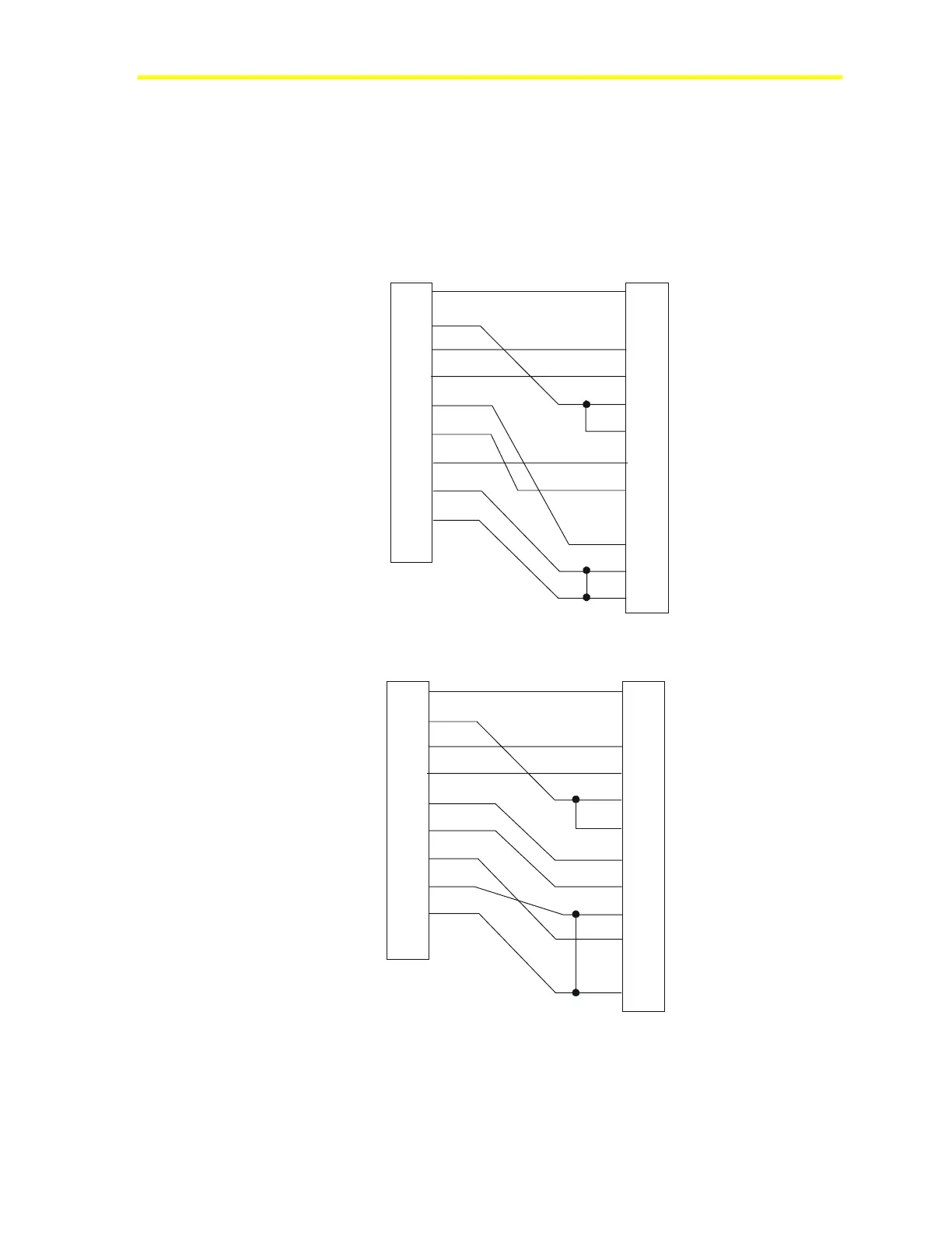
Cable connections from Port 2 of an NCM using the Gateway program
set require one of two configurations: one for 101, 110, or 112 models
of the JC/85 (top illustration), and one for 111 or 113 models (bottom
illustration).
1
2
3
4
5
6
7
8
9
DCD
RXD
TXD
DTR
SG
DSR
RTS
CTS
NC
NCM
9-pin Female
1
2
3
4
5
6
7
8
20
22
25
JC/85/40
25-pin Male
For Models
101, 110, or 112
1
2
3
4
5
6
7
8
9
DCD
RXD
TXD
DTR
GND
DSR
RTS
CTS
NC
NCM
9-pin Female
1
2
3
4
5
6
7
8
20
22
25
JC/85/40
25-pin Male
For Models
111 or 113
nc3fig15
Shell
TD
RD
RTS
CTS
DTR
SG
DSR
DCD
TD
RD
RTS
CTS
DSR
SG
DCD
DTR
Shell
Shell Shell
Figure 18: Gateway NCM Port 2 to JC/85 Headend RS-232 Port