P470 Electronic Pressure Control with Display Product/Technical Bulletin6
Adjustments
This section provides instructions for setting up and
adjusting the P470 control using the internal jumpers
and front panel touchpad.
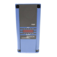
Positioning the Jumpers
The P5 jumper-pin terminal has a single pair of jumper
pins and is used to lock or unlock the touchpad. The P6
jumper-pin terminal has two pairs of jumper pins and is
used to establish the control’s operating pressure
range.
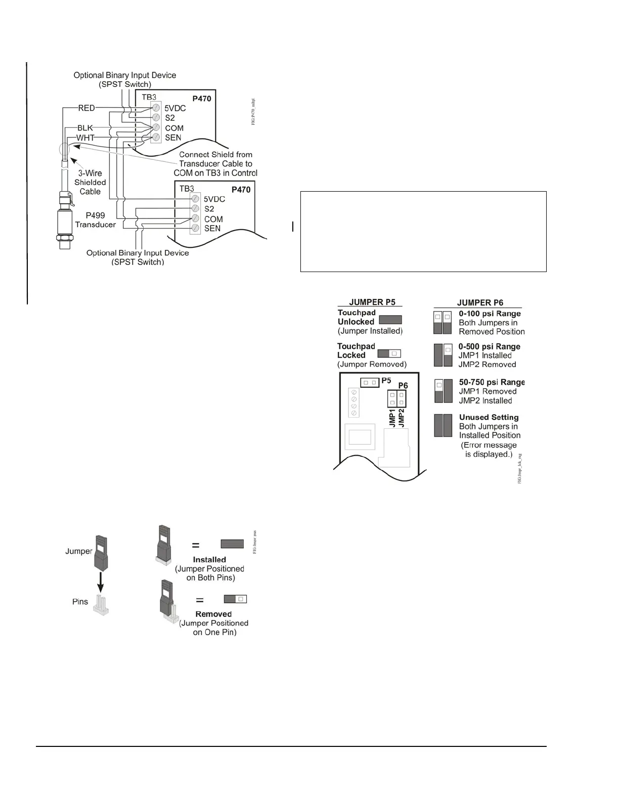
To position a jumper in the Installed position, place the
jumper on both pins. To position a jumper in the
Removed position, place the jumper on only one pin.
(Save the jumper in case it is required in the future.)
See Figure 8.
Set the jumpers as follows, using Figure 8 and Figure 9
as guides.
1. Disconnect all power sources to the P470 control.
2. Remove the control’s cover by loosening the
four captive cover screws.
3. Position the jumpers to set the desired operating
pressure range and lock or unlock the touchpad.
4. Replace the cover, and restore power to the
control.
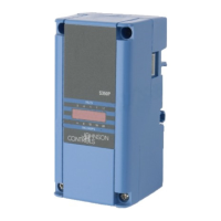
Figure 7: Wire Multiple P470 Controls in Parallel
with a Single Transducer
Figure 8: Positioning the Jumpers
IMPORTANT: The P470 control’s three field-
selectable operating pressure ranges require
specific P499 transducer models for the control to
operate properly. Do not use a transducer model
that is not specified for the P470 control’s field-
selected operating pressure range. See Table 2.
Figure 9: Jumper Positions for Locking
Touchpad and Establishing the P470 Control’s
Operating Pressure Range