P470 Electronic Pressure Control with Display Product/Technical Bulletin8
Scrolling through the Adjustable Setpoints
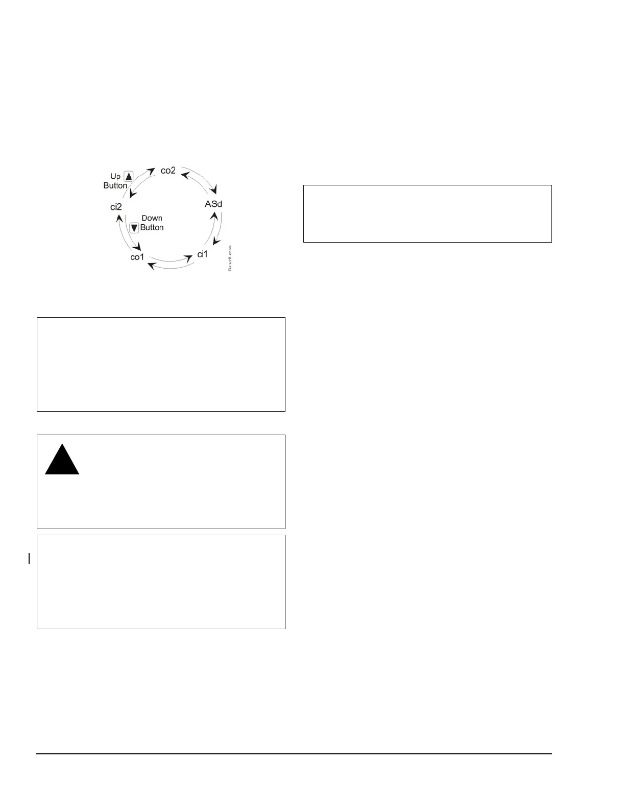
Figure 10 illustrates the order of the adjustable
setpoints displayed when scrolling through them using
the Up or Down buttons. Press the Up button to scroll
through and display the adjustable setpoints in a
clockwise direction. Press the Down button to scroll
through and display the adjustable setpoints in a
counterclockwise direction.
Troubleshooting
Determine what the proper supply voltage is for the
control you are troubleshooting. See Figure 4,
Figure 5, and Figure 6 for the wiring diagram and
terminal designations for the control.
See Figure 3 and Table 3 for more information about
displayed codes (error codes) that appear on the LCD.
On dual control applications, disconnect one control
and check each control as a single control application
using the following procedures. See Figure 7.
Equipment Needed
• An accurate and reliable pressure gauge
connected near the transducer.
• A reliable and accurate Digital Voltmeter (DVM)
capable of measuring AC voltage and DC voltages
down to ± 0.1 VDC in the 0–10 VDC range.
1. Check for proper supply voltage to the control.
a. Before powering control and equipment, check
that all of the wiring is correct and all of the
connections are tight.
b. Apply power to the control.
c. With the DVM, check the voltage between the
control’s supply power terminals: T1 and T2 for
the low-voltage model, and AC COM and 120V
or 240V for the line voltage model.
• For low-voltage controls powered by a 24 VAC
Class 2 transformer, select AC volts on the
DVM. The supply voltage must be between
20–30 VAC.
• For line-voltage controls, select AC volts on the
DVM. The supply voltage must be between
102–132 VAC for controls powered at the 120V
and COM terminals, and between 177–264
VAC for controls powered at the 240V and
COM terminals.
d. If the voltage reading is within the specified
voltage range, proceed to Step 2.
e. If the DVM reading is not within the indicated
voltage ranges, replace the 24 VAC Class 2
transformer or check the line voltage power
source and provide for proper power to the
control.
f. Recheck for proper supply voltage.
2. Check for proper supply voltage to the pressure
transducer.
a. Select DC volts on the DVM and measure the
voltage (VDC
S
) between 5VDC and the COM
terminals on the terminal block on the upper
left side of the control.
IMPORTANT: Before applying power to the control
and controlled equipment, make sure installation,
wiring, and control settings are according to the
application requirements. Then power the
equipment and observe the controlled equipment for
at least three complete operating cycles before
leaving the installation.
WARNING: Risk of Electric Shock.
Do not touch any exposed metal parts
with anything other than properly
insulated tools or insulated probes of the
digital voltage meter. Failure to use
properly insulated tools and probes may
result in severe personal injury or death.
IMPORTANT: The P470 pressure control and
P499 transducer are not field repairable. Perform
the following procedures, in the order they are
presented, to determine the problem. If the problem
is with the control or transducer, contact a
Johnson Controls/PENN sales representative for a
replacement.
Figure 10: Order of the Adjustable Setpoints and
Time Delay Interval
IMPORTANT: The control and the controlled
equipment must be powered and operating at a
stable pressure to perform many of the following
procedures.