P470 Electronic Pressure Control with Display Product/Technical Bulletin 9
b. The voltage must be 5.0 VDC (± 0.2 VDC).
If the voltage is in this range, proceed to
Step 3.
• If the voltage is out of this range, power down
the controlled equipment and disconnect it
from the control. Disconnect the transducer
from the control. With the control powered,
measure the voltage (VDC
S
) between the
5VDC and COM terminals on the terminal
block on the upper left side of the control.
• The voltage must be 5.0 VDC (± 0.2 VDC).
If the voltage is in this range, replace the
transducer. If the voltage is out of range,
replace the P470 control.
3. Check pressure transducer for proper output signal
voltage.
a. Measure and record the voltage (V
o
) between
the SEN and the COM terminals on the control
terminal block.
b. At the same time, observe and record the
pressure reading (psi
T
) on the gauge.
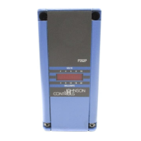
c. The transducer output signal voltage (V
o
)
increases proportionally with an increase in the
pressure at the transducer (psi
T
). Use the
graph in Figure 11 to compare the measured
signal voltage to the measured pressure or use
the formula below to compare the voltage and
pressure values.
psi
T
= Pressure measured at transducer
V
o
= Transducer output signal voltage (VDC)
VDC
S
= Supply voltage to the transducer
(measured in Step 2a).
P
max
= Transducer pressure range maximum
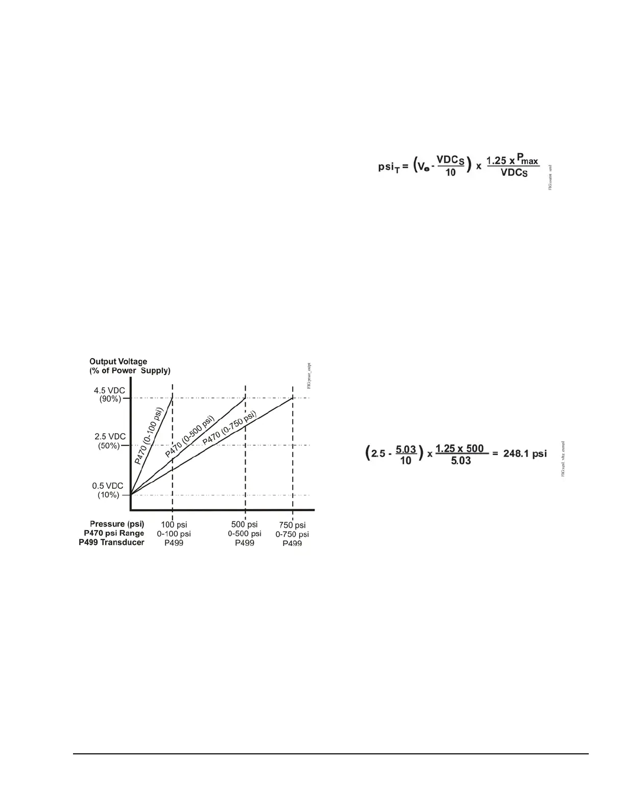
Example:
The measured pressure at the gauge is
approximately 245 psi (psi
T
), the measured
transducer output voltage is 2.5 VDC (V
o
), the
measured supply voltage to the transducer is
5.03 VDC (VDC
S
), and the transducer’s rated
range is 0 to 500 psi (P
max
). Use the formula
above to calculate the pressure you would expect
from the measured voltage.
Since the measured pressure, psi
T
(245 psi), is
close to the pressure (248.1 psi) calculated from
the measured voltage, the transducer output
voltage is considered acceptable.
Note: Depending on the accuracy of the
instrumentation used to measure the actual
pressure at the transducer (psi
T
) and the
transducer output voltage (V
o
), the actual and
calculated pressure may not exactly agree.
4. Check the control for proper operation.
Perform Steps 1-3 first.
Note: The pressure range jumpers must be
positioned to operate the control in a pressure
range that is compatible with the transducer used.
See Table 2.
Figure 11: Pressure vs. Output Voltage
Figure 12: Output Signal Voltage
Figure 13: Output Signal Voltage Example