P470 Electronic Pressure Control with Display Product/Technical Bulletin10
Note: When the LED is lit, the output relay should
be energized and the N.O. contacts should be
closed.
Note: Use the minimum differential value for the
selected operating pressure range. See Table 2.
Note: The following procedures change the cut-in
and cutout setpoints and shift the setpoint
differential so the displayed pressure is not within
the Setpoint Differential range. See Figure 14 and
Figure 15.
a. Set the P470 control’s anti-short cycle delay to
0 (zero), and make sure that the control is
operating on the primary setpoints (S1).
b. Disconnect power to the controlled equipment
and allow the pressure in the unpowered
equipment to stabilize at a pressure of 30 psi
or more above the minimum pressure for the
selected operating pressure range.
c. Disconnect the wires from the P470 control’s
output relay, and make sure the control is
powered.
d. The pressure displayed on the control should
equal the pressure measured at the transducer
with a pressure gauge. If the two pressure
value differ greatly, check the gauge for
accuracy. If the gauge checks out, replace the
control and recheck display and measured
pressure.
e. (See Figure 14.) If the control is operating as
an open-high control and:
• The LED is Off. Increase cutout setpoint
above the displayed pressure by the minimum
differential pressure (for the selected operating
pressure range) plus 10 psi. Then increase the
cut-in setpoint above the displayed pressure
by 5 psi. The LED should go On (and the N.O.
contacts close).
• The LED is On. Decrease cut-in setpoint
below the displayed pressure by the minimum
differential pressure plus (for the selected
operating pressure range) 10 psi. Then
decrease the cutout setpoint below displayed
pressure by 5 psi. The LED should go Off
(and the N.O. contacts open).
f. For example, if the control and transducer are
setup for a 0–100 psi pressure range with a
40 psi cut-in setpoint and a 50 psi cutout, and
the displayed pressure is 47 psi, the LED may
be On or Off. Adjust the cutout up to 62 psi (or
higher) and the cut-in up to 52 psi (or higher).
The LED should be On. Then adjust the cut-in
down to 32 psi (or lower) and the cutout down
to 42 psi (or lower). The LED should go Off.
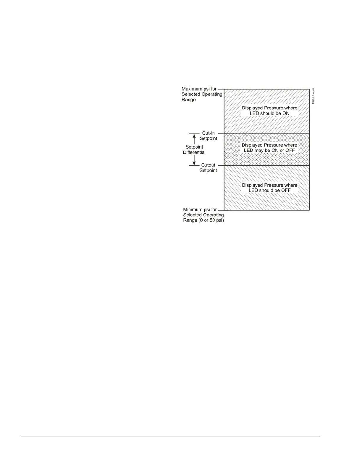
g. This procedure, in effect, moves the
crosshatched areas shown on the graphs in
Figure 14 and Figure 15 above or below the
displayed pressure, and forces the LED to go
On or Off (and output relay to close or open)
and verifies the control is functioning properly.
(See Figure 15.) If the control is operating as
an open-low control and:
• The LED is Off. Decrease cutout setpoint
below the displayed pressure by the minimum
differential pressure (for the selected operating
pressure range) plus 10 psi. Then decrease
the cut-in setpoint below the displayed
pressure by 5 psi. The LED should go On (and
the N.O. contacts close).
Figure 14: LED Status for Open-High Controls