RL SERIES INSTALLATION MANUAL
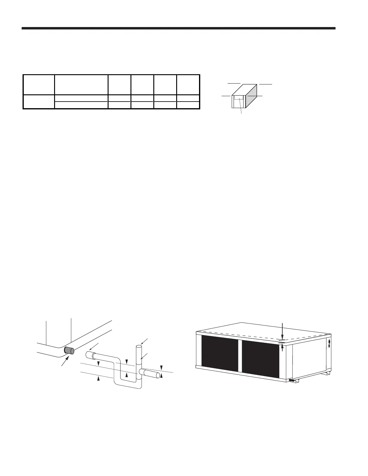
1/2'' Pitch
Figure 5: Unit Pitch for DrainFigure 4: Suggested Layout of Condensate
Installing Horizontal Units cont.
ABCD
Front Front Back Back
Model Return / Discharge Left Right Right Left
Left / Side or End 30% 26% 22% 22%
Right / Side or End 26% 30% 22% 22%
Approximate
080 - 120
A
B
C
D
Controls
Horizontal Unit Corner Weight Distribution
Duct System
An air outlet collar is provided on vertical top flow units and all horizontal units to facilitate a duct connection. A flexible connector is recom-
mended for discharge and return air duct connections on metal duct systems. Uninsulated duct should be insulated with a minimum of
1-inch duct insulation. Application of the unit to uninsulated ductwork in an unconditioned space is not recommended as the unit’s perfor-
mance will be adversely affected.
If the unit is connected to existing ductwork, check the duct system to ensure that it has the capacity to accommodate the air required for
the unit application. If the duct is too small, as in the replacement of heating only systems, larger ductwork should be installed. All existing
ductwork should be checked for leaks and repaired if necessary.
The duct system should be sized to handle the design airflow quietly and efficiently. To maximize sound attenuation of the unit blower, the
supply and return plenums should include an internal duct liner of fiberglass or constructed of ductboard for the first few feet. On systems
employing a sheet metal duct system, canvas connectors should be used between the unit and the ductwork. If air noise or excessive
airflow is a problem, the blower speed can be changed.
Water Piping
The proper water flow must be provided to each unit whenever the unit operates. To assure proper flow, use pressure/temperature ports to
determine the flow rate. These ports should be located at the supply and return water connections on the unit. The proper flow rate cannot
be accurately set without measuring the water pressure drop through the refrigerant-to-water heat exchanger.
All source water connections on commercial units are fittings that accept a male pipe thread (MPT). Insert the connectors by hand, then
tighten the fitting with a wrench to provide a leakproof joint. When connecting to an open loop (groundwater) system, thread any copper
MPT fitting into the connector and tighten in the same manner as described above.
1.5 in.
1.5 in.
3/4 in. PVC tube stub
3/4 in. PVC
Coupling
Vent (if needed)
3/4 in. PVC
1/8 in. per foot