Engineering manual - SAB 193-233-283 S A-frame (including ATEX)
008831 en 2020.10
55/168
Technical description
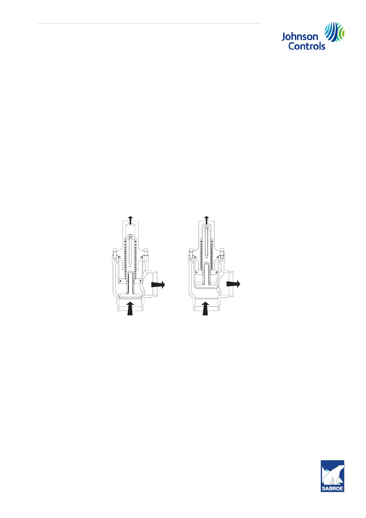
Once the compressor is running it will begin to force gas to the condenser at connection P2.
As the condenser heats up, the pressure will begin to rise as the compressor suction pulls down in
pressure. As soon as a differential pressure has developed between the condenser and suction
side, these pressures will act across a piston inside the cold-start valve to partially overcome the
spring force. When the differential pressure reaches and exceeds 2.0 bar [30 psi], the piston fully
overcomes the spring force and powers the valve fully open for a very low operating pressure
drop.
Booster applications
For booster applications, the valve is equipped with a light spring, which produces 0.5 bar [7 psi]
oil pressure above suction pressure before it fully powers open. An oil pump is required to ensure
compressor lubrication.
The unit is also equipped with a suction check valve by-pass. The oil separator will slowly bleed
down to approximate system suction pressure when the unit is stopped. This allows the compres-
sor drive motor to have an easier start, and the discharge check valve will seat more tightly. See
section 4.18 Suction check valve by-pass for operation.
Note: For alarm descriptions and shutdown or cut-out parameters, see separate control system
manual.
Fig. 32: Cold-start valve
O
pen
Closed
P3 - To suction
P2 - To
condenser
P1 - From
oil separator
P1
P2
P3
 Loading...

