RWF II ROTARY SCREW COMPRESSOR UNITS
INSTALLATION
070.610-IOM (JUN 11)
Page 8
The oil filter(s) and coalescer element(s) shipped with the
unit are best suited to ensure proper filtration and operation
of the system.
SUCTION ISOLATION VALVE MOUNTING
The suction isolation valve is shipped loose from the factory,
so it can be installed at various positions within the suction
line piping to the compressor. DO NOT INSTALL the valve
at the compressor suction with ow against the cone/but-
ton (see Figure 2). When the isolation valve is installed in
this position, uneven ow is generated across the suction
check valve which is mounted at the inlet to the compres
sor. This uneven ow causes the disks in the check valve
to strike against the stop pin, and eventually damage the
internals of the check valve. If the isolation valve is mounted
at the compressor suction, DO INSTALL with ow across
the cone/button (see Figure 3). Please design your system
piping accordingly.
Figure 2 - INCORRECT Valve Installation
Figure 3 - CORRECT Valve Installation
THERMOSYPHON OIL COOLING
Thermosyphon oil cooling is an economical, effective method
for cooling oil on screw compressor units. Ther mosyphon
cooling utilizes liquid refrigerant at condenser pressure and
temperature that is partially vaporized at the condenser tem
perature in a plate and shell vessel, cooling the oil to within
35°F of that temperature. The vapor, at condensing pressure,
is vented to the condenser inlet and reliquied. This method
is the most cost effective of all currently applied cooling
systems since no compres sor capacity is lost or compressor
power penalties in curred. The vapor from the cooler need
only be con densed, not compressed. Refrigerant ow to the
cooler is automatic, driven by the thermosyphon principle
and cooling ow increases as the oil inlet temperature rises.
EQUIPMENT The basic equipment required for a ther
mosyphon system consists of:
1. A source of liquid refrigerant at condensing pressure and
temperature, located in close proximity to the unit to mini
mize piping pressure drop. The liquid level in the refrigerant
source must be 6 to 8 feet minimum above the center of the
oil cooler.
2. A plate and shell oil cooler with:
Plate Side: Oil 400 psi design
Shell Side: Refrigerant 400 psi design
Due to the many variations in refrigeration system design
and physical layout, several systems for assuring the above
criteria are possible.
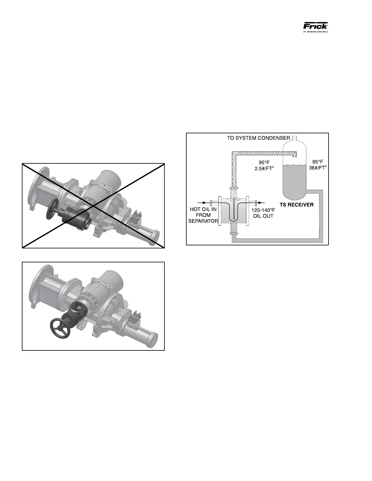
Figure 4
SYSTEM OPERATION - Liquid refrigerant fills the cooler
shell side up to the Thermosyphon receiver liquid level.
Hot oil (above the liquid temperature) flowing through the
cooler will cause some of the refrigerant to boil and vaporize.
The vapor rises in the return line. The density of the refriger-
ant liquid/vapor mixture in the return line is considerably less
than the density of the liquid in the supply line. This imbalance
provides a differential pressure that sustains a flow condi tion
to the oil cooler. This relationship involves:
1. Liquid height above the cooler.
2. Oil heat of rejection.
3. Cooler size and piping pressure drops.
Current thermosyphon systems are using two-pass oil cool-
ers and flow rates based on 3:1 overfeed.
The liquid/vapor returned from the cooler is separated in the re-
ceiver. The vapor is vented to the condenser inlet and need only
be reliquified since it is still at condenser pressure (Figure 4).
OIL TEMPERATURE CONTROL - Oil temperature will gen-
erally run about 15 - 35°F above condensing tempera ture.
In many cases, an oil temperature control is not required if
condensing temperature is above 65°F as oil tempera ture
can be allowed to float with condenser temperature.
Condensing Temperature: 65°F - 105°F
Oil Temperature: 80°F - 140°F
INSTALLATION The plateandshell type thermosyphon oil
cooler with oilside piping and a thermostatically controlled
mixing valve are factory mount ed and piped. The customer
must supply and install all piping and equip ment located
INCORRECT!
CORRECT!