TEC2145-4 N2 Networked Thermostat Controller with Single Proportional Output and One-Speed Fan
Control Installation Instructions
3
Wiring
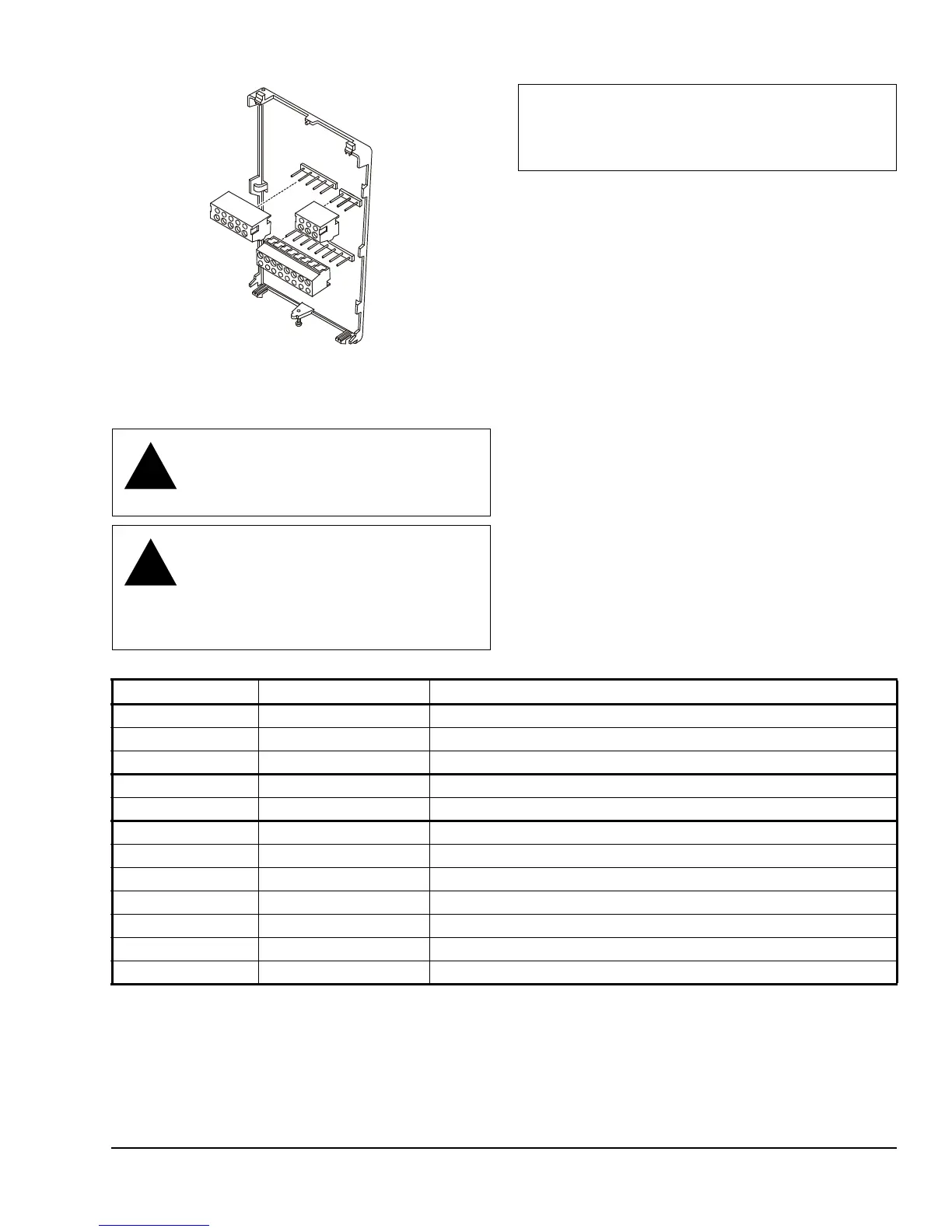
When an existing thermostat controller is replaced,
remove and label the wires to identify the terminal
functions. When a TEC2145-4 Thermostat Controller is
replaced, simply remove the old screw terminal blocks
and reinsert them onto the PCB of the replacement
thermostat controller.
To wire the thermostat controller:
1. Strip the ends of each wire 6 mm (1/4 in.) and
connect them to the appropriate screw terminals as
indicated in Table 1 and Figure 5.
2. Carefully push any excess wire back into the wall.
Note: Seal the hole in the wall with fireproof
material to prevent drafts from affecting the
ambient temperature readings.
3. Reinsert the screw terminal blocks onto the PCB.
4. Reattach the N2 communication wires to the
terminal block.
Note: If multiple wires are inserted into the
terminals, be sure to properly twist the wires
together prior to inserting them into the terminal
connectors.
CAUTION: Risk of Electric Shock.
Disconnect power supply before making
electrical connections to avoid electric
shock.
CAUTION: Risk of Property Damage.
Do not apply power to the system before
checking all wiring connections. Short
circuited or improperly connected wires
may result in permanent damage to the
equipment.
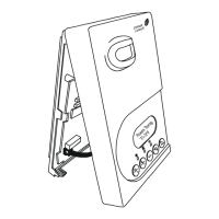
Figure 4: Removing the Screw Terminal Blocks
F
I
G
:
t
r
m
n
l
_
b
l
c
k
s
IMPORTANT: Make all wiring connections in
accordance with local, national, and regional
regulations. Do not exceed the electrical ratings of
the TEC2145-4 Thermostat Controller.
Table 1: Terminal Identification (See Figure 5.)
Terminal Number Terminal Label Function
3 Fan Fan On
4 24 V~ Hot 24 VAC from Transformer
5 24 V~ Com 24 VAC (Common) from Transformer
6 BO5 Aux Aux BO (Auxiliary Output)
7 BO5 Aux Aux BO (Auxiliary Output)
10 AO1 Analog Output 0 to 10 VDC
11 Blank Blank
12 BI1 Configurable Binary Input 1
14 Scom Sensor Common
15 BI2 Configurable Binary Input 2
16 UI3 Configurable Universal Input 3
Blank +, -, REF N2 Bus