TEC2664Z-3 BACnet® MS/TP Rooftop Controller for Stand-Alone and Networked Zoning Systems
Installation Instructions
5
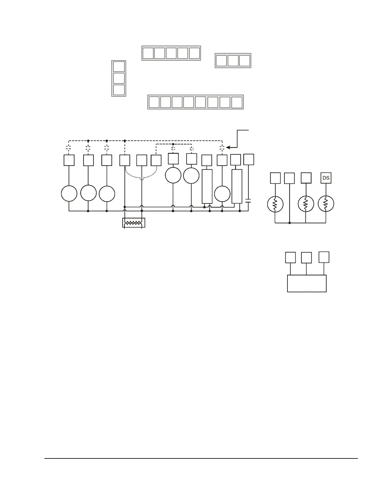
Figure 6: Wiring the TEC2664Z-3 Rooftop Controller
(See Table 1.)
+
REF
Supervisory
Jumper
If the same power source is used for the
rooftop controller and the heating loads,
install a jumper across RC and RH.
RH
W1
W2
AU
Aux
DI1SP
Auxiliary Contact for:
• Lighting
• On/Off Actuation
• Exhaust Fan
BPD
0 to 5
VDC
Heating
Stage
II
G
Fan
Output
Scom
OS
Outside
Discharge
Remote Inputs
Return
Air
Sensor
Cooling
Stage
II
Cooling
Stage
I
Heating
Stage
I
REF
–
+
MS/TP
Connector
RH W1 W2
Three-Pole
Right Top
Connector
6 7 8
DI1
Eight-Pole Bottom Connector
9 10 11 12 13 14 15 16
Five-Pole
Left Top Connector
Common
0 to 10
VDC
24 VAC
24 VAC
Common
24 VAC
Rooftop Controller
Power