TEC3000 Series Proportional Fan Coil and Individual Zone Thermostat Controllers with Dehumidification
Capability Installation Instructions
10
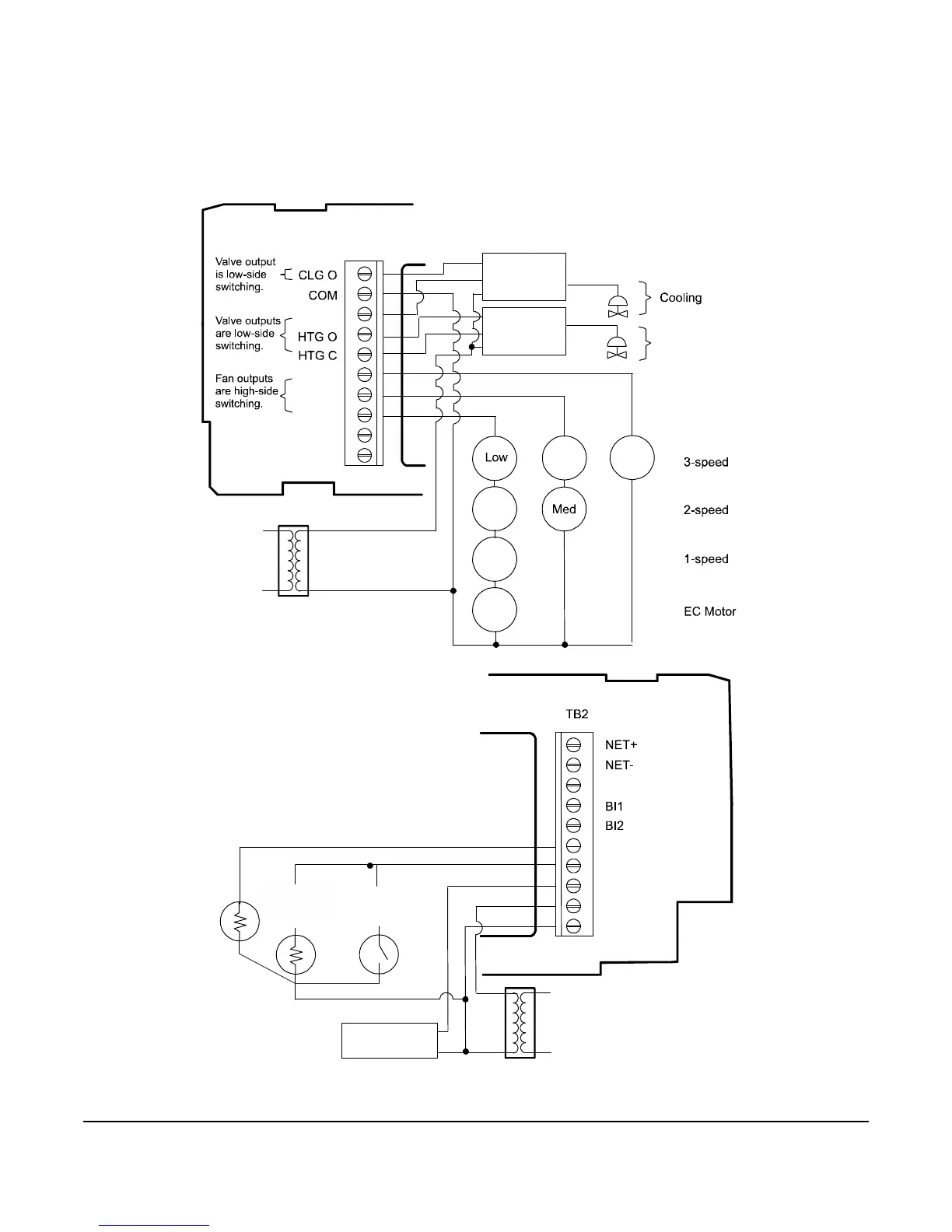
Note: VAV and 2-pipe systems should connect their valve to the heating output.
Figure 8: Proportional 0 to 10 VDC Control (Pressure-Dependent VAV)
Figure 9: Proportional 0 to 10 VDC Control
(Pressure-Dependent VAV with Changeover Sensor/Switch)
Figure 10: Proportional 0 to 10 VDC Control
(Pressure-Dependent VAV with Changeover Sensor/Switch and Reheat)
Note: Power to the AUX contact comes from the reheat coil.
Room Temperature Control Thermostat
(Minimum and Maximum Position
Adjusted on Actuator)
Proportional
Actuator
FIG:model_2_clng_only
FIG:model_2_htng_clng_chngvr
Changeover
Sensor
Room Temperature Control Thermostat
(Minimum and Maximum Position
Adjusted on Actuator)
Proportional
Actuator
Supply Air
Temperature Sensor
FIG:model_2_htng_clng_chngvr_rht
Changeover
Sensor
Room Temperature Control Thermostat
(Minimum and Maximum Position
Adjusted on Actuator)
Heating/Cooling
and On/Off
Duct Heater
Proportional
Actuator
Supply Air
Temperature Sensor
VDC
COS
COM
24V
HTG
AUX*
AUX*
*The Reheat Installed parameter
must be set to True.