VA9208-GGx-x Series Proportional Electric Spring Return Valve Actuators Installation Instructions6
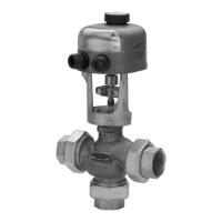
6. Insert fixed pointer and M4x0.7x83 mm long screw
into the Side A actuator hub. Direct the arrow on
the pointer to 100%.
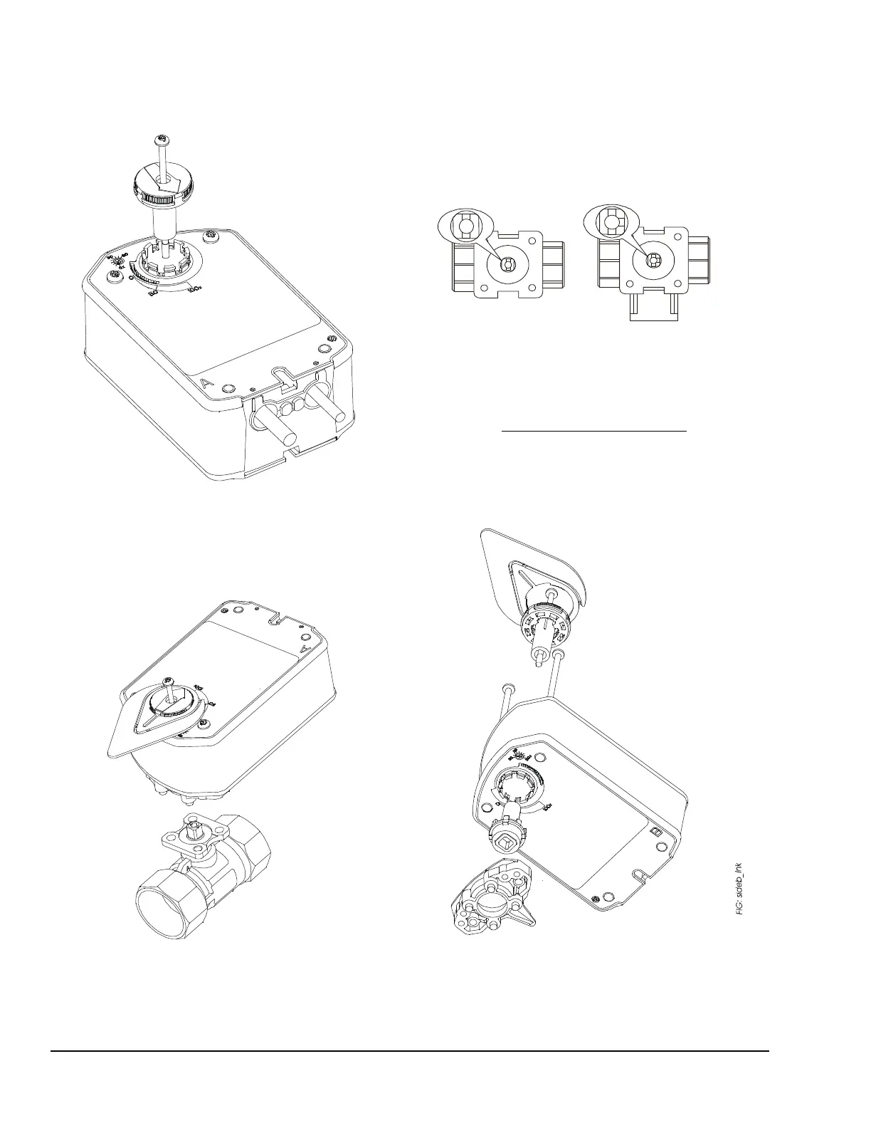
7. Install the actuator on the ball valve (Figure 9).
Tighten the actuator mounting screw to a torque of
10 to 12 lb·in. (1.1 to 1.4 N·m) and snap the large
adjustable pointer into place.
Mounting the Actuator to Spring Return Port A
(Coil) Closed
To mount the actuator to spring return port A (coil)
closed:
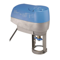
1. Turn the valve stem to the position outlined in
Figure.
2. Mount optional M9000-561 Thermal Barrier to the
valve if fluid temperature exceeds 212°F (100°C).
See the Mounting the Thermal Barrier
section for
more information.
Note: Proceed to Step 7 if the ball valve linkage is on
actuator Side A.
3. Remove the linkage from Side B (Figure 11).
Figure 8: Installing the Fixed Pointer
Figure 9: Mount the Actuator
Figure 10: Positioning the Valve Stem
Figure 11: Removing the Linkage

 Loading...