18 Installation Guide
www.johnsoncontrols.com Issue Number: 2
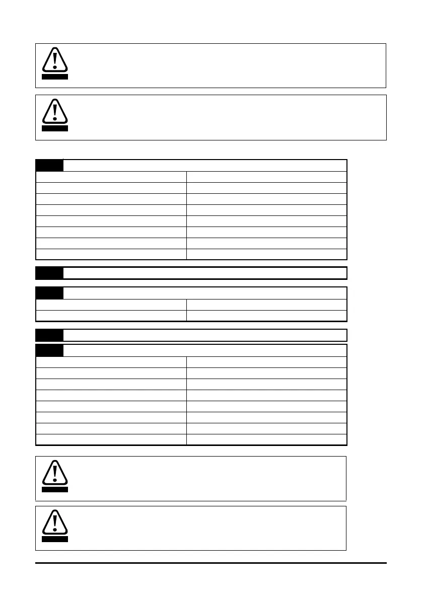
4.4 Control terminals I/O specification
4.4.1 Control connections
The control circuits are isolated from the power circuits in the drive by basic insulation
(single insulation) only. The installer must ensure that the external control circuits are
insulated from human contact by at least one layer of insulation (supplementary
insulation) rated for use at the AC supply voltage.
If the control circuits are to be connected to other circuits classified as Safety Extra Low
Voltage (SELV) (e.g. to personal computer), an additional isolating barrier must be
included in order to maintain the SELV classification.
T1
PWM control input (C)
Range 0-10V
Resolution 0.1%
Accuracy ±3%
Logic positive logic only
Nominal threshold voltage 5V
Input impedance 660Ω
Sample time 6ms
Frequency 10Hz
T2
Not connected
T3
Fault output (F) (normally closed)
On state current 500μA minimum at 2.5V
Off state leakage current 50μA maximum at 5V
T4
Fault return (FR)
T5
PWM control return (CR)
Range 0-10V
Resolution 0.1%
Accuracy ±3%
Digital input positive logic only
Nominal threshold voltage 5V
Input impedance 660Ω
Sample time 6ms
Frequency 10Hz
The drive will perform a single automatic restart, 25 seconds after the trip
condition.
A flywheel diode should be installed across inductive dc loads connected to
the fault output e.g. relay coil.