Installation Guide 19
Issue Number: 2 www.johnsoncontrols.com
Safety information Operation Mechanical installation Electrical installation
Operation
Technical specifications UL listing information
5 Operation
5.1 Drive configuration
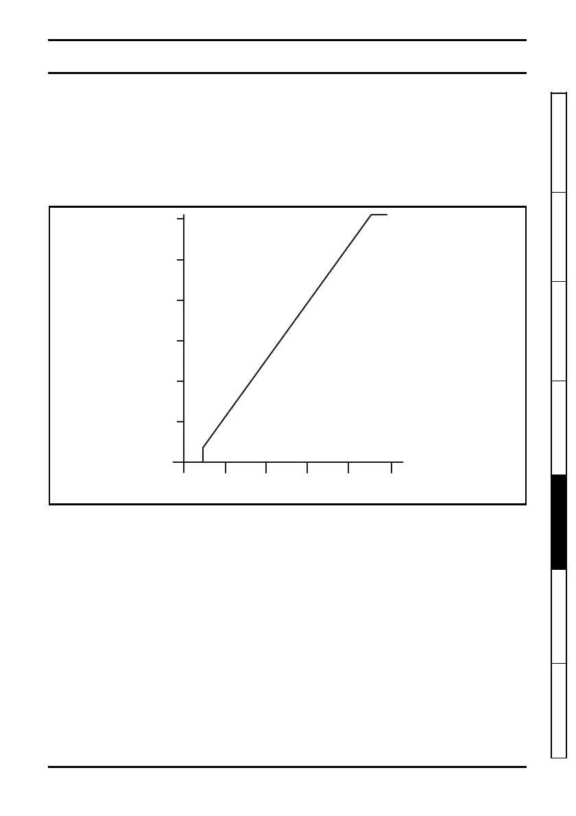
Input signal: The drive has only one digital input, which is a 10Hz, PWM speed reference. The duty
cycle of this signal determines the speed of the motor.
Duty cycle high time from 0 to 7% will cause the inverter output to be off. Output (3Hz minimum
frequency) will begin between 7% and 13% duty cycle and reaching 60 Hz output with 87% to 93%
duty cycle; maintain 60Hz output from 93% to 100% duty cycle.
Figure 5-1 Output frequency Vs. input duty cycle
5.2 Line starting capabilities:
The drive will start automatically when line power is applied, even if the motor is already rotating.
5.3 Repairs and replacements
Field repairs of the VFD66 Control should not be made. In case of a defective or improperly
functioning control, contact your nearest Authorized Johnson Controls/PENN® Distributor or Sales
Representative. When contacting your Johnson Controls/PENN distributor, have the model number
of the control available. This number can be found on the label on the side of the control.
0
20
40
60
10
30
50
Output frequency (Hz)
Duty cycle (%)