EasyManua.ls Logo

Johnson Controls YC2E - User Manual

Johnson Controls YC2E
22 pages
Print Icon
To Next Page IconTo Next Page
Loading...
Johnson Controls Ducted Systems
R-410A Outdoor Split-System Air
Conditioning
York International Corporation, 5005 York
Drive, Norman, OK 73069
2022-01-10
6158110-UIM-A-0122
Supersedes: nothing
A
Question and Answer IconNeed help?

Do you have a question about the Johnson Controls YC2E and is the answer not in the manual?

Summary

General Information

Certification

Details on product certifications and standards compliance.

Safety Precautions

Explains safety alert symbols and signal words for hazard identification.

Transit Inspection

Procedures for inspecting units for damage during transit.

Installation Limitations

Outlines restrictions for installation and operation to ensure performance.

Unit Installation and Location

Site Selection and Clearance

Guidance on selecting and preparing a suitable installation site for units.

Liquid Line Filter-Drier Installation

Outdoor Unit Filter-Drier Mounting

Step-by-step guide for installing a filter-drier on the outdoor unit.

Indoor Coil Filter-Drier Mounting

Step-by-step guide for installing a filter-drier on the indoor coil.

Refrigerant Piping Connections

Line Installation Precautions

Important safety and procedural advice for installing refrigerant lines.

Refrigerant Line Brazing

Line Brazing Safety

Essential safety measures for brazing refrigerant lines.

Service Valve Brazing Safety

Safety guidelines for brazing around service valves to prevent damage.

Connecting Refrigerant Lines

Metering Device Selection

Information on selecting and installing metering devices like TXV or piston.

Thermostatic Expansion Valve (TXV) Installation

System Evacuation Procedure

Procedure for evacuating the system to remove moisture and air.

Refrigerant System Charge

Guidelines for determining and adding refrigerant charge.

Indoor Airflow Measurement

Steps to measure and verify correct indoor airflow for system performance.

System Charging Procedures

Subcooling Charging for TXV Systems

Optional Cold Weather Charging

Electrical Connections and Grounding

Control Box Access and Grounding

Details on grounding requirements and control box access.

Electrical Connections

Power Wiring Installation

Steps for connecting the main power supply to the unit.

Control Wiring Installation

Steps for connecting low voltage control wiring to the unit.

Field Wiring Guidelines

User Instruction and System Maintenance

End-User Operation Guidance

Guidance for installers on educating the end-user about the system.

Routine Maintenance Tasks

Key maintenance activities for ensuring optimal system performance.

Wiring Diagrams Overview

Start-Up Sheet Details

Owner and Contractor Information

Section for recording owner and installation contractor details.

Equipment Identification Data

Fields for recording model and serial numbers for equipment.

Filter, Thermostat, and Accessories Setup

Details for filter type, size, location, and thermostat type.

Installation Code Compliance Checks

Checklist for verifying installation compliance with codes and instructions.

Line Voltage Electrical Setup

Specifications and checks for the unit's line voltage connections.

Low Voltage Electrical Setup

Requirements and checks for low voltage wiring and thermostat connections.

Heating System Configuration

Information related to setting up the heating functionality of the system.

Ventilation System Requirements

Guidelines for properly sizing and installing ventilation systems.

Start-Up Sheet: System Pressures and Settings

Cooling Blower Configuration

Settings and configurations for the indoor blower in cooling mode.

Heating Blower Configuration

Settings and configurations for the indoor blower in heating mode.

Refrigerant Charge Data Entry

Fields for recording refrigerant charge, metering device, and line set details.

Operational Cycle Testing

Procedures for testing the unit's operation in various modes.

Post-Installation Cleanup

Checklist for post-installation site cleanup.

Owner Education Checklist

Key points for educating the owner on system operation and maintenance.

Installation Comments

Area for adding any relevant notes or comments about the installation.

Overview

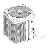
This document describes the R-410A Outdoor Split-System Air Conditioning unit, providing comprehensive instructions for its installation, operation, and maintenance.

Function Description:

The R-410A Outdoor Split-System Air Conditioning unit is designed to be connected to a matching indoor coil to provide air conditioning. It utilizes R-410A refrigerant, which operates at higher pressures than R-22 systems. The unit is equipped with a filter-drier located in the liquid line. Units with quick-connect coupling connections are factory charged with refrigerant to be matched with appropriate pre-charged line sets and indoor coils. The system is designed for residential and light commercial applications, providing cooling by transferring heat from the indoor environment to the outdoors. The outdoor unit's fan is a propeller type and is not designed to operate against additional external static pressure, meaning it should not be installed with ductwork in the air stream.

Important Technical Specifications:

  • Refrigerant: R-410A. This refrigerant operates at higher pressures than R-22, requiring compatible service equipment and components.
  • Filter-Drier: A liquid line filter-drier (part S1-401021 for all AC models) is included and must be installed. It can be installed at either the outdoor unit or the indoor coil, preferably before the refrigerant metering device. Granular type driers are not recommended due to potential equipment damage.
  • Piping: Uses field-supplied refrigerant grade (ACR) copper tubing that is internally clean and dry. The charge given is applicable for total tubing lengths up to 15 ft (4.6 m). For longer lengths (exceeding 80 ft or 22.86 m), refer to the Piping Application Guide (P/N 24077) for line sizing, pressure loss/gain calibration, vapor line velocity, elevation limitations, TXV connections, and charging. Vapor lines must be insulated with a minimum of 3/8 in. foam rubber insulation. Liquid lines exposed to direct sunlight, high temperatures, or excessive humidity must also be insulated.
  • Electrical Connections: All field wiring must use copper conductors and comply with Local, National, Fire, Safety, and Electrical Codes. The unit must be grounded with a separate ground wire. Power wiring, control (low voltage) wiring, disconnect switches, and overcurrent protection must be supplied by the installer and sized according to NEC requirements. The control box is designed to swing open for service access.
  • Operating Conditions:
    • Outdoor Coil Ambient Air Temperature: Minimum 55°F DB (Dry Bulb), Maximum 125°F DB. Operation below 55°F requires an approved low ambient operation accessory kit.
    • Indoor Coil Air Temperature: Minimum 57°F DB, Maximum 72°F DB.
    • Maximum Allowable Line Length: 80 ft.
  • Charging: The factory charge includes enough refrigerant for the unit, 15 ft (4.6 m) of interconnecting piping, and the smallest indoor coil match-up. Additional charge may be required for specific indoor coil matches or longer line lengths, determined by referring to the Tabular Data Sheet. Charging procedures include subcooling charging for TXV indoor units, which involves measuring indoor wet bulb and outdoor ambient dry bulb temperatures and comparing liquid pressure to recommended values. Optional cold weather charging procedures are provided for temperatures of 55°F or below, involving the use of a charging tent.
  • Thermostatic Expansion Valve (TXV): If a TXV kit is installed, outdoor unit models ending with an "H" require a factory-installed hard start kit. The Schrader valve core must not be installed into the suction line TXV equalizer line fitting. The TXV temperature sensing bulb must be mounted on the vapor line near the equalizer tube connection port, at a 10 o'clock or 2 o'clock position, and insulated to protect it from ambient temperature.

Usage Features:

  • Installation Flexibility: The filter-drier can be installed at either the outdoor unit or the indoor coil.
  • Service Access: The outdoor unit's control box is designed to swing open, facilitating easy service of refrigeration components. A flexible electrical connection is required for this swing-away function.
  • Refrigerant Line Management: Instructions are provided for proper routing and insulation of refrigerant lines to minimize noise transmission and prevent liquid refrigerant buildup during shutdown. PVC piping is recommended for underground installations.
  • System Charging: Detailed instructions for measuring indoor airflow and charging the system, including subcooling charging for TXV indoor units and optional cold weather charging, ensure optimal performance.
  • Safety Features: Warnings and cautions are prominently displayed throughout the manual, emphasizing the importance of proper installation, handling of R-410A refrigerant, and electrical safety. These include precautions against using R-22 service equipment, improper brazing techniques, and venting refrigerant into the atmosphere.

Maintenance Features:

  • User Instruction: Installers are required to instruct the user on correct operation and maintenance, including starting, stopping, temperature adjustment, and the function of the crankcase heater (if equipped).
  • Coil Cleaning: Outdoor coils and other air circuit parts should be cleaned regularly with a brush or vacuum cleaner attachment to prevent dirt accumulation. Clean water can be used to wash dust, dirt, and debris from the outdoor coil. Coil cleaners containing hydrogen fluoride (HF), hydroxides, chlorides, and sulfates are not to be used on micro channel coils as they can reduce their lifetime.
  • Fan Motor: The outdoor fan motor is permanently lubricated and does not require periodic oiling.
  • Indoor Coil and Drain Pan: These components must be inspected and cleaned regularly to prevent odors and ensure proper drainage.
  • Filter and Blower Motor: Maintenance instructions for these components are found in the furnace or air handler manuals.
  • Regular Inspections: The manual emphasizes the importance of regular filter replacement and equipment maintenance.
  • Start-up Sheet: A detailed start-up sheet is provided for recording installation and operational parameters, which is crucial for proper system setup and future troubleshooting. This includes sections for equipment data, connections, electrical readings, heating setup, venting, refrigerant charge, cycle tests, and owner education.

Johnson Controls YC2E Specifications

General IconGeneral
BrandJohnson Controls
ModelYC2E
CategoryAir Conditioner
LanguageEnglish

Related product manuals