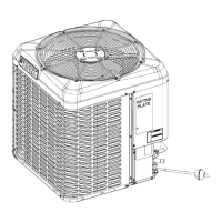
8. Install the TXV bulb to the vapor line near the TXV
equalizer tube connection port, using the bulb
clamps supplied with the TXV assembly. Ensure
that the bulb makes maximum contact. See Figure
9 and Figure 10 and adhere to the following:
a. Install the TXV bulb on the vapor line
suction header near the TXV equalizer tube
connection port. Ensure that the bulb is
installed at a 10 o’clock or 2 o’clock position.
b. Insulate the TXV bulb using the thermal
insulation provided to protect it from
the effect of the surrounding ambient
temperature. Cover the bulb completely to
insulate it.
9. When the refrigeration piping is installed, leak test
the system.
Figure 9: TXV bulb and equalizer line installation
Figure 10: Correct bulb location for TXV
Evacuation
It is necessary to evacuate the system to 500 microns or
less. If a leak is suspected, leak test with dry nitrogen to
locate the leak. Repair the leak and test again.
To verify that the system has no leaks, close the valve to
the vacuum pump suction to isolate the pump and hold
the system under vacuum. Watch the micron gauge for
a few minutes. If the micron gauge indicates a steady
and continuous rise, it is an indication of a leak. If the
gauge shows a rise, then levels off after a few minutes
and remains fairly constant, it is an indication that the
system is leak free but still contains moisture and may
require further evacuation if the reading is above 500
microns.
System charge
To ensure that this system performs at the published
levels, it is important that the indoor airflow is determined
and refrigerant charge is added accordingly.
Measuring indoor airflow
About this task:
To determine rated airflow for a specific
match, consult the technical literature at
www.simplygettingthejobdone.com. When attempting to
match this airflow, select the lowest possible speed tap,
measure the actual airflow, and adjust as necessary.
To measure actual airflow, it is not an acceptable method
to just check the jumper pin setting tables and to assume
0.5 in. W.C. total external static pressure.
To determine indoor airflow, complete the following
steps:
1. Measure the static pressure with a manometer
between the filter and blower.
R-410A Outdoor Split-System Air Conditioning 13
Johnson Controls Ducted Systems