Important: To avoid interference, assign a unique PAN setting to each wireless network in a
building. Using a unique PAN setting is particularly important if you have PANs on adjacent
floors of a building. Do not use the same PAN OFFSET on multiple wireless networks in a
building, even if the PANs do not overlap.
Router LEDs Functional Definition
Table 2: Router LEDs Functional Definition
ZFR1831 State Color Description
Blue/Green Powering up
Off Network
Blue/Blip Searching for Network to join
On Network - Normal State Green Normal Operation
On Network - Warning State Purple Steady Dim Warning (Lost Coordinator)
Red Blink Open for Joining
Yellow Blink Standby (PB Enabled)
Green Blink Normal
On Network - Commissioning
State
Purple Blink Warning (Lost Coordinator)
White
Join PB being pressed (user
feedback)
Miscellaneous
Aqua Firmware Update in progress
Technical specifications
Table 3: ZFR1831 Router (used as Coordinator, Controller, and Repeater)
Product code number ZFR1831-0: Wireless Field Bus Router
Power supply input 15VDC with cable connected to field controller, or 24 VAC (nominal, 20
VAC minimum/30 VAC maximum), 50/60 Hz, power supply Class 2.
Addressing Rotary Switches, Field Adjustable
Wireless band Direct-Sequence Spread-Spectrum, 2.4 GHz ISM Bands
Transmission power 100 mW Maximum (selectable)
Transmission range 75m (250ft) Maximum at 100mW
1200m (4000ft) Maximum Line-of-Sight
Ambient conditions Operating: -40°C to 75°C (-40°F to 167°F), 5% to 95% RH,
Noncondensing
Storage: -40°C to 85°C (-50°F to 185°F), 5% to 95% RH,
Noncondensing
Materials White Plastic Housing with Plenum rating per UL2043, UL94-5VA
Flammability Rating
Terminations RJ-12 plug or 4-pin terminal
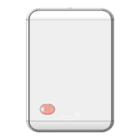
Dimensions 127 mm x 85.7 mm x 31.75 mm (5 in. x 3-3/8 in. x 3/4 in.)
Mounting hardware Conduit: 1/2 in. trade size Electrical Mechanical Tubing (EMT)
connector
Wall or Gang Box: Screw mounted
Ceiling Grid: T-Track clip (Grainger Item #45DN38 or equivalent). See
https://www.grainger.com/for more information.
ZFR1831 Pro Series Wireless Router Installation Guide10
Johnson Controls - CONFIDENTIAL
 Loading...