Do you have a question about the Johnson 40-6502 and is the answer not in the manual?
Lists the items included in the product package for both models.
Details the capabilities and operational features of the laser level.
Crucial safety warnings and precautions for laser operation and user protection.
Important notes on safe operation, handling, and avoiding hazards.
Identifies the location and content of hazard warning labels on the unit.
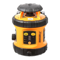
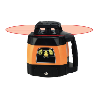
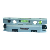
Illustrates and labels the different parts and components of the laser level.
Step-by-step guide for operating the laser level controls and modes.
Steps to attach the laser unit to its base for setup and tripod mounting.
Guide on how to insert the required "AA" batteries into the unit.
Procedure for centering the vial bubbles using leveling knobs.
Instructions for using the laser level in its horizontal mode.
Instructions for using the laser level in its vertical mode.
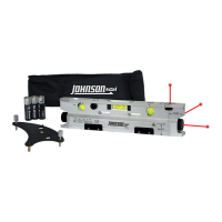
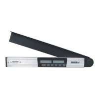
Lists technical details for the laser detector accessory.
Identifies the structural parts and display elements of the detector.
Steps for installing batteries into the laser detector.
Explains how to use the detector to find the laser beam.
Information on connecting the detector to other accessories like a grade rod.
Guidelines for cleaning and caring for the laser detector.
Procedure for verifying and adjusting the laser level's calibration.
Steps to calibrate the X and Y vials using leveling knobs and hex key.
Detailed technical data for the main laser level unit.
Visual examples of how to use the laser level in various scenarios.
Recommendations for proper handling and storage of the laser unit.
Details the limited warranty terms and conditions for the product.
Instructions on how to register the product for warranty coverage.
Information on purchasing and using optional accessories for the laser level.
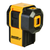
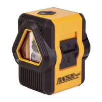
This document describes a manual-leveling rotary laser level, available in two models: 40-6502 and 40-6512. The device is designed for various leveling and alignment tasks, emitting a laser beam that can be used for both horizontal and vertical applications.
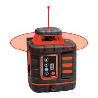
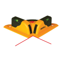
The primary function of this device is to project a laser plane for accurate leveling. It can emit a horizontal laser plane, useful for tasks like ceiling installation or anti-static flooring. Additionally, it can emit a vertical laser plane with a simultaneous 90° split beam, which is beneficial for applications such as window installation or baseboard alignment. The laser also features large and small scan modes that create a visible chalk line, and the scan line can be moved clockwise or counter-clockwise to suit specific needs. The rotation speed of the laser is variable, allowing users to adjust it based on the visibility requirements or the distance of the project. The device is housed in a rugged casing, ensuring durability during use.
Before using the laser level, it is crucial to read and understand all safety instructions to avoid injury and prevent voiding the warranty. The device is a Class IIIa laser product with a maximum power output of ≤ 5mW and a wavelength of 625-645nm. Users are warned not to stare directly into the beam or project it into the eyes of others. It should not be set up at eye level or operated near reflective surfaces. The laser tool should be kept out of reach of children and untrained persons. It is not suitable for use in explosive environments.
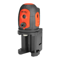
To operate the laser, it must first be connected to its base. This involves positioning the two slots on the laser into the base and tightening the locking knob. Once secured, the laser can be mounted on a tripod.
Battery installation requires disconnecting the laser from its base by rotating the base unlock/lock knob counterclockwise. The battery cover is then removed by rotating its knob counterclockwise. Four "AA" alkaline batteries are inserted according to the specified polarity, and the battery cover is reattached.
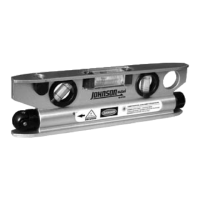
For horizontal usage, the laser is placed on a flat surface or a 5/8" - 11 tripod. The X-vial and Y-vial leveling knobs are adjusted to center the bubbles, ensuring the laser is level. After leveling, the laser is turned on. Once the work is complete, the laser should be turned off.
For vertical usage, the laser is placed on a flat surface or a 5/8" - 11 tripod, as shown in the manual. The Z-vial leveling knob is adjusted to center the bubble. The laser is then turned on and turned off after use.
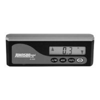
The device features a keypad with several controls:
The Model 40-6512 includes a detector for extended range use. The detector has a horizontal vial for accurate positioning. When detecting, the middle signal indicator turns red, then green, and beeps once to indicate it's on. If the battery is low, the horn will give two short sounds and power off, or the down signal indicator will flash. The detector's signal indicators show whether the laser beam is up, down, close to center, or exactly at center, accompanied by different sound signals (single short sound, solid sound, or no sound). The detector automatically powers off after 6 minutes if no laser signal is received or no buttons are pushed. The detector can be connected to a grade rod bracket, ensuring the top of the bracket is level with the back reference marker line.
Proper care and handling are essential for maintaining the precision and longevity of the laser level.
For the detector:
The user is responsible for verifying the instrument's calibration before each use. Calibration involves a self-check procedure for the X and Y vials. This process requires placing the laser 50 feet from a wall, leveling the vials, marking the laser beam's position (X+), rotating the laser 180 degrees, marking the new position (X-), and measuring the distance between X+ and X-. If the distance exceeds 1/8 inch, calibration is needed. The calibration method involves marking the middle point between X+ and X- as O and adjusting the X vial leveling knob to align the beam with point O. A 2.5 Metric Hex Key is used to remove the X vial screw and adjust the vial bubble to the middle. The same procedure is repeated for the Y vial.
| Brand | Johnson |
|---|---|
| Model | 40-6502 |
| Category | Laser Level |
| Language | English |