24 ©2017 Johnson Level & Tool - Rev. 1
the laser line is within 3/32” of Point 0. Loosening this screw
will bring the laser line UP as viewed when the X-axis is point-
ed towards the wall. Tightening the adjustment bolt will bring
the laser line DOWN in this orientation.
3. After adjusting the X-direction, adjust the Y-direction using the
same method. Loosening the Y direction adjustment bolt will
bring the laser line UP the wall in the direction of the Y-axis,
tightening will bring the laser line DOWN the wall.
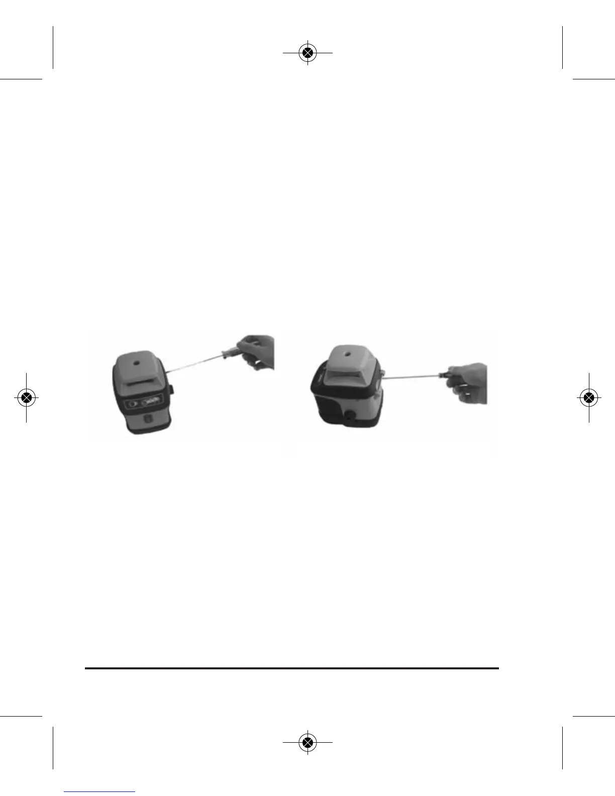
4. After the laser is calibrated, reinstall the adjustment-hole
bolts and complete the steps above for X & Y direction
accuracy verification to confirm the changes you have made.
Accuracy Self-Check for Plumb Beam
1. After completing the above steps to field adjust the rotary
laser output, double check the plumb beam output. Because
the optics for the plumb beam are shared with the optics for
the rotary, if the rotary is in calibration, the plumb beam
should also be in calibration, so this step is really a redundant
check; no further adjustment to the plumb beam is possible.
2. Place the instrument horizontally on a rotating tripod head so
that the plumb beam strikes the ceiling. The higher the ceiling,
Remove the adjustment-hole bolt Adjust the fine adjustment bolt
1658i-English_Manuals 1/11/17 11:50 AM Page 24