Do you have a question about the Johnson 40-6519 and is the answer not in the manual?
Instructions for installing batteries in the laser unit, including removing the cover and ensuring correct polarity.
How to turn the laser on and off, and interpret the power LED indicator status (on, off, low battery).
Procedure for cycling through low, medium, and high rotation speeds and understanding the corresponding LEDs.
Guidance on switching between manual and self-leveling modes and the conditions for self-leveling.
Steps to attach the leveling base and adjust the laser for vertical use using the bubble level.
Procedure to check the accuracy of the laser's horizontal and vertical beams by marking points and measuring distances.
Detailed steps for adjusting the laser's X and Y directions using fine-adjustment bolts to correct calibration errors.
Method to verify the calibration of the vertical plumb beam by marking points on the ceiling after rotating the laser.
Steps to adjust the laser's internal vial to ensure accurate leveling, using a hex wrench for fine adjustments.
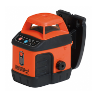
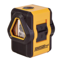
This document describes the Johnson Self-Leveling Rotary Laser, Model No. 40-6519, a Class IIIa laser tool designed for various leveling and alignment tasks. It complies with CRF 21, parts 1040.10 and 1040.11, as well as international safety rule IEC 285. Users are advised to read the manual thoroughly before operation and save it for future reference.
The rotary laser features a self-leveling system with magnetically dampened compensation, ensuring accuracy and ease of use. If the laser is tilted beyond its self-leveling range, rotation will stop, and an alarm will sound to alert the user. This feature helps prevent inaccurate measurements. The device can project either a horizontal laser plane with a vertical plumb beam or a vertical laser plane with a simultaneous 90° split beam, offering versatility for different applications.
The laser offers three rotation speeds: 200rpm (Low), 400rpm (Medium), and 600rpm (High), allowing users to select the appropriate speed for visibility and detection needs. An illuminated vial is included for precise alignment when operating in the vertical plane. The unit is designed to be water and dust resistant, enhancing its durability in various working environments.
For operation, the laser requires six "AA" alkaline batteries. Battery installation involves unscrewing the battery cover in a clockwise direction, inserting the batteries according to the polarity indicated, closing the cover, and screwing it in counter-clockwise to lock. It is crucial to ensure the compensator lock knob is in the "Off" position before removing or replacing batteries.
To power on/off the laser, a dedicated button is pressed. A lighted LED indicates power is on, while an extinguished LED means power is off. A flashing LED signals low batteries, prompting the user to change them. The rotating speed can be adjusted by pressing a separate button, cycling through high, medium, and low speeds, with a corresponding LED illuminating for the selected speed. The laser defaults to high-speed mode upon startup. Low speed is recommended for indoor use to maximize beam visibility, while high speed is ideal when using a detector outdoors.
For manual operation, the lock knob should be turned counter-clockwise to the "Off" position, which locks the compensator and disables self-leveling. To enable self-leveling, the lock knob is turned clockwise to the "On" position. The laser should be placed on a relatively smooth, flat, and level surface. For the self-leveling feature to work correctly, the laser must be within ±3° of level. If it exceeds this range, it will stop rotating and emit an intermittent beeping sound.
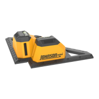
When using the laser in vertical mode, a bubble level adjustment is necessary. First, the lock knob is turned counter-clockwise to "Off" to lock the compensator. The laser is then held by its hand grips, and the horizontal vial adjustment knob is inserted into its receiver. The leveling base connecting bar receiver is gently pressed into the laser's connecting bar until the clip spring activates. The assembly is placed on a smooth, flat surface, and the adjustment knob is turned to center the bubble in the vial.
Important notes for usage include setting the lock knob to "Off" when the laser is in horizontal manual mode. After operation or before moving the unit, always power off the laser and set the lock knob to "Off" to prevent damage to the laser assembly during transport. If storing the laser for more than three months, remove batteries from both the laser and the detector.
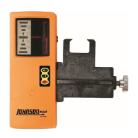
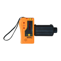
The detector, an accessory for the rotary laser, has its own set of features and maintenance guidelines. It can detect a red rotating laser beam. To turn it on, the Power Key is pressed once; the middle signal indicator will turn red, then green, and a single beep will confirm it's on. During detection, signal indicators show the laser beam's position relative to the detector: lower red LED for "up," upper red LED for "down," orange middle LED for "close to center," and green middle LED for "exactly to center." Different sound patterns (single short sound, solid sound, or no sound) also indicate the beam's position.
Battery installation for the detector involves opening the battery cover, inserting two "AAA" alkaline batteries according to polarity, and snapping the cover back. If the detector powers off automatically after two short sounds, the battery voltage is low and needs immediate replacement. If the down signal indicator flashes, batteries are low and should be replaced soon. For optimal accuracy when detecting a horizontal laser beam, the detector's horizontal bubble vial should be centered. The detecting window should always face the rotating laser, and the detector should be kept still during detection. If the detector doesn't receive a laser signal for 6 minutes and no buttons are pressed, it will power off automatically after the middle signal indicator turns green then red, accompanied by two short sounds.
Accessories for the detector include a grade rod bracket and a grade rod, allowing for versatile mounting and measurement.
Maintenance of the detector involves keeping it clean, especially the detecting window, by gently wiping it with a clean cloth if dusty. Users should avoid dropping or knocking the unit. While rain resistant, submerging the unit in water or other liquids should be avoided; if contact occurs, wipe it dry immediately. The detector should not be used near fire or exposed to it.
The manual also provides application demonstrations for the 40-6519, highlighting its utility for tasks such as installing wood or metal stud walls (horizontal for reference heights, vertical for plumb or layout), laying out wall and floor tile (both horizontally and vertically), aligning shelving, cabinets, or stacked photos (vertically), leveling shelving, cabinets, or rows of photos (horizontally), aligning tape for pinstriping, grading areas with a detector, building retaining walls, laying out fencing or posts, and installing drop ceilings.
Calibration is a critical aspect of maintaining the laser's accuracy. Users are responsible for verifying the instrument's calibration before each use. The X- and Y-direction accuracy verification involves placing the laser on a level platform 25' from a wall, powering it on, unlocking the compensator, setting the rotation speed to low, and marking the top edge of the beam (Point Ax). After rotating the laser 180 degrees, a second point (Point Bx) is marked in the same vertical plane. The center point (Point Ox) between Ax and Bx is then marked. If the distance between Ax and Bx exceeds 3/16" at 25', the laser is out of calibration. The same process is repeated for the Y-direction.
Accuracy calibration involves turning off the laser and unlocking the compensator. Adjustment-hole bolts are removed with a #1 Philips screwdriver, and a 3mm hex wrench is used to adjust the X-direction fine-adjustment bolt. Loosening the screw moves the laser line UP, and tightening moves it DOWN. The Y-direction is adjusted similarly. After calibration, the adjustment-hole bolts are reinstalled, and the accuracy verification steps are repeated to confirm the changes.
A self-check for the plumb beam is also outlined. After calibrating the rotary laser, the plumb beam output should be double-checked. The instrument is placed horizontally on a rotating tripod head so the plumb beam strikes the ceiling. The higher the ceiling, the more accurate the check. The point where the plumb beam hits the ceiling is marked. The laser is rotated 90 degrees, and the spot is marked again. This is repeated twice for a total of four marks. If these four points form a circle with a diameter less than 3/16" at 25', the laser is in calibration. If the plumb beam is out of calibration but the rotary beam is calibrated, the laser requires servicing by an authorized Johnson dealer.
Vial calibration involves adjusting the laser to project a perfectly vertical beam on a wall, marking two points, and using a calibrated bubble level to validate verticality. If the vial needs adjustment, a screwdriver is used to remove the vial level adjustment bolt cover, and a 2.5mm hex wrench is inserted into the adjustment hole. Rotating the hex wrench clockwise moves the bubble AWAY from the adjustment screw, while loosening moves it TOWARDS the adjustment screw. After calibration, the vial adjustment bolt cover is reinstalled.
Johnson Level & Tool offers a three-year limited warranty on its products. Users can obtain a copy of the warranty from their website or Customer Service Department. Non-warranty repairs and course calibration must be performed by an authorized Johnson service center to maintain warranty validity. For warranty repairs, a Return Material Authorization (RMA) is required, along with proof of purchase.
For further assistance or issues not covered in the manual, users in the U.S. can contact Johnson Level & Tool's Customer Service Department at 888-9-LEVELS, and in Canada at 800-346-6682. Warranty registration is encouraged within 30 days of purchase to ensure service information is on file and to receive product recall notifications. Registration can be done at www.johnsonlevel.com/register.
Johnson accessories are available through authorized dealers. Using non-Johnson accessories will void any applicable limited warranty. Assistance in locating accessories can be obtained from the Customer Service Department.
| Model | 40-6519 |
|---|---|
| Category | Measuring Instruments |
| Type | Digital Multimeter |
| Power Source | 9V Battery |
| Battery Test | Yes |
| Display Type | LCD |
| Units of Measure | Volts, Amps, Ohms |
| DC Voltage Range | 200mV, 2V, 20V, 200V, 600V |
| AC Voltage Range | 200V, 600V |
| DC Current Range | 10A |
| Resistance Range | 200Ω, 2kΩ, 20kΩ, 200kΩ, 2MΩ |